Table of Contents
- 1. Product Overview
- 2. Technical Parameter Deep-Dive Analysis
- 2.1 Absolute Maximum Ratings
- 2.2 Electro-Optical Characteristics
- 2.2.1 Input Diode Characteristics
- 2.2.2 Output Transistor Characteristics
- 2.3 Transfer Characteristics
- 3. Grading System Explanation
- 4. Performance Curve Analysis
- 5. Mechanical & Package Information
- 6. Soldering & Assembly Guidelines
- 7. Packaging & Ordering Information
- 8. Application Recommendations
- 8.1 Typical Application Scenarios
- 8.2 Design Considerations
- 9. Technical Comparison & Differentiation
- 10. Frequently Asked Questions (Based on Technical Parameters)
- 11. Practical Design Example
- 12. Operating Principle
- 13. Technology Trends
- LED Specification Terminology
- Photoelectric Performance
- Electrical Parameters
- Thermal Management & Reliability
- Packaging & Materials
- Quality Control & Binning
- Testing & Certification
1. Product Overview
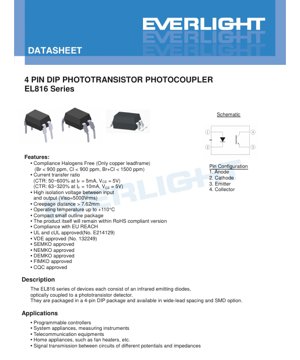
The EL816 series represents a family of industry-standard 4-pin Dual In-line Package (DIP) phototransistor photocouplers. These devices are designed to provide reliable electrical isolation and signal transmission between circuits of different potentials. Each unit integrates an infrared emitting diode optically coupled to a silicon phototransistor detector within a single, compact package.
The core function is galvanic isolation, preventing ground loops, blocking high-voltage transients, and allowing signal transfer between circuits with different reference grounds or voltage levels. The series is characterized by its robust construction, offering high isolation voltage and a wide range of Current Transfer Ratio (CTR) grades to suit various application needs, from simple on/off detection to linear signal transfer.
2. Technical Parameter Deep-Dive Analysis
2.1 Absolute Maximum Ratings
These ratings define the stress limits beyond which permanent damage may occur. The device is not intended for operation at these extremes.
- Input (LED Side): The infrared diode has a maximum continuous forward current (IF) of 60 mA. A brief 1 A pulse (1 µs duration) is permissible. The maximum reverse voltage (VR) is 6 V, emphasizing the need for proper polarity protection.
- Output (Transistor Side): The phototransistor can handle a collector current (IC) of 50 mA and a collector-emitter voltage (VCEO) of 80 V. The lower emitter-collector voltage (VECO = 6V) indicates the asymmetry of the phototransistor junction.
- Isolation & Thermal: A key specification is the isolation voltage (VISO) of 5000 Vrms for 1 minute, tested with pins 1-2 shorted and pins 3-4 shorted. The device operates from -55°C to +110°C and can withstand soldering at 260°C for 10 seconds.
- Power Dissipation: Total device dissipation (PTOT) is 200 mW. The input diode can dissipate 100 mW without derating up to 100°C. The output transistor is rated for 150 mW, requiring derating above 80°C at 5.8 mW/°C.
2.2 Electro-Optical Characteristics
These parameters define the device's performance under normal operating conditions (Ta = 25°C unless noted).
2.2.1 Input Diode Characteristics
- Forward Voltage (VF): Typically 1.2V, with a maximum of 1.4V at IF = 20 mA. This is used for calculating current-limiting resistor values.
- Reverse Current (IR): Maximum 10 µA at VR = 4V, indicating good diode reverse characteristics.
- Input Capacitance (Cin): Up to 250 pF, which can affect high-frequency drive circuit design.
2.2.2 Output Transistor Characteristics
- Dark Current (ICEO): The leakage current with the LED off is a maximum of 100 nA at VCE = 20V, defining the "off-state" noise floor.
- Breakdown Voltages: BVCEO ≥ 80V and BVECO ≥ 6V, confirming the voltage blocking capability.
2.3 Transfer Characteristics
These are the most critical parameters for application design, defining the relationship between input current and output current.
- Current Transfer Ratio (CTR): This is the ratio of output collector current (IC) to input forward current (IF), expressed as a percentage. The EL816 series offers a wide selection of CTR grades, tested at standard conditions (IF = 5mA, VCE = 5V for most, IF = 10mA for I/J/K grades). Ranges include:
- EL816: 50% to 600% (broad, ungraded)
- EL816A: 80% to 160%
- EL816B: 130% to 260%
- EL816C: 200% to 400%
- EL816D: 300% to 600%
- EL816X: 100% to 200%
- EL816Y: 150% to 300%
- EL816I: 63% to 125% (at IF=10mA)
- EL816J: 100% to 200% (at IF=10mA)
- EL816K: 160% to 320% (at IF=10mA)
- Saturation Voltage (VCE(sat)): Typically 0.1V (max 0.2V) at IF=20mA, IC=1mA. This low value is crucial for digital switching applications to achieve a solid "low" logic level.
- Isolation Resistance & Capacitance: RIO > 5×10¹⁰ Ω and CIO < 1.0 pF. The high resistance ensures minimal leakage, while the low capacitance is vital for maintaining high Common-Mode Transient Immunity (CMTI) in noisy environments.
- Frequency Response: The cut-off frequency (fc) is typically 80 kHz, defining the useful bandwidth for analog signal transmission.
- Switching Speed: Rise time (tr) and fall time (tf) are typically 4 µs and 3 µs respectively (max 18 µs each) under specified test conditions (IC=2mA, RL=100Ω). This determines the maximum digital switching frequency.
3. Grading System Explanation
The EL816 series employs a precise grading system based solely on Current Transfer Ratio (CTR).
- CTR Grading: Devices are sorted into bins (A, B, C, D, X, Y, I, J, K) based on their measured CTR at the specified test current. This allows designers to select a part with guaranteed gain limits, improving circuit consistency and yield. For example, choosing an EL816C (200-400%) ensures a higher minimum gain than an EL816A (80-160%), which may allow for a lower LED drive current or provide more output current headroom.
- No Wavelength/Color Grading: As the emitter is an infrared diode, visible wavelength or color grading is not applicable. The phototransistor is sensitive to the IR spectrum emitted by its matched LED.
4. Performance Curve Analysis
While specific curves are not detailed in the provided text, typical performance trends for such devices are analyzed below based on the stated parameters.
- CTR vs. Forward Current (IF): CTR is not constant; it typically peaks at a specific IF and decreases at very low or very high currents. The specification of CTR at both 5mA and 10mA (and 1mA for some grades) hints at this non-linearity. Designers should operate near the test condition for predictable gain.
- CTR vs. Temperature: CTR generally has a negative temperature coefficient; it decreases as temperature increases. The wide operating temperature range (-55°C to +110°C) necessitates considering this derating in designs intended for extreme environments.
- Switching Time vs. Load Resistance (RL): The specified tr and tf are with RL=100Ω. Switching speed is heavily influenced by RL and any parasitic capacitance. A smaller RL will typically speed up turn-off but may increase power dissipation.
- Forward Voltage vs. Temperature: The diode VF has a negative temperature coefficient, dropping approximately 2 mV/°C. This is a minor effect compared to the CTR temperature dependence.
5. Mechanical & Package Information
The series offers multiple package options to accommodate different PCB assembly processes and spacing requirements.
- Standard DIP Type: The classic through-hole package with standard lead spacing.
- Option M Type: A through-hole package with a "wide lead bend," providing a 0.4-inch (approx. 10.16mm) lead spacing for increased creepage/clearance or compatibility with specific sockets.
- Option S1 Type: A "low profile" surface-mount (SMD) lead form. It is supplied on tape and reel (TU or TD) with 1500 units per reel.
- Option S2 Type: Another SMD low-profile lead form, with a different footprint and supplied on tape and reel with 2000 units per reel.
- Creepage Distance: Exceeds 7.62 mm, which is critical for meeting safety standards for reinforced insulation at high isolation voltages.
- Device Marking: Packages are marked with "EL" (manufacturer code), "816" (device number), a letter for CTR Rank (R), and a 1-digit year code (Y) plus week (WW).
6. Soldering & Assembly Guidelines
Based on the absolute maximum ratings and package options.
- Soldering Temperature: The device can withstand a peak soldering temperature of 260°C for 10 seconds. This is compatible with standard lead-free (SnAgCu) reflow profiles.
- Moisture Sensitivity: While not explicitly stated in the excerpt, SMD components (S1, S2 options) typically have a Moisture Sensitivity Level (MSL). It is critical to follow the manufacturer's handling instructions, including baking if exposed to ambient air beyond the specified time, to prevent "popcorning" during reflow.
- Storage Conditions: The storage temperature range is -55°C to +125°C. Components should be stored in a dry, controlled environment.
- Recommended Pad Layout: The datasheet provides specific land pattern recommendations for the S1 and S2 surface-mount options. Using these is essential for reliable solder joint formation and mechanical stability.
7. Packaging & Ordering Information
The part number follows the format: EL816X(Y)(Z)-FV
- X (Lead Form): S1, S2, M, or none (standard DIP).
- Y (CTR Rank): A, B, C, D, X, Y, I, J, K, or none (ungraded).
- Z (Tape & Reel): TU, TD (for SMD options), or none.
- F (Lead Frame): F for Iron, blank for Copper.
- V: Optional VDE safety certification mark.
Packing Quantities: Through-hole parts are supplied in tubes of 100 units. SMD parts are on tape and reel: 1500 units/reel for S1, 2000 units/reel for S2.
8. Application Recommendations
8.1 Typical Application Scenarios
- Programmable Logic Controllers (PLCs): Isolating digital I/O modules from the central processing unit and field devices.
- System Appliances & Measuring Instruments: Providing isolation in power supplies, data acquisition systems, and test equipment.
- Telecommunication Equipment: Isolating signal lines in modems, interfaces, and network equipment.
- Home Appliances: Used in control circuits for appliances like fan heaters, washing machines, etc., for safe low-voltage control of mains-connected parts.
- General Signal Transmission: Any application requiring voltage level shifting or ground loop elimination between circuits.
8.2 Design Considerations
- LED Current Limiting: Always use a series resistor to set IF. Calculate Rlimit = (VCC - VF) / IF. Operate near the CTR test condition (5mA or 10mA) for predictable gain.
- Output Loading: The load resistor (RL) on the collector affects switching speed, output swing, and power dissipation. A smaller RL gives faster turn-off but lower output voltage swing and higher IC.
- Noise Immunity: For digital applications, ensure a sufficient CTR margin so that the "on-state" IC fully saturates the transistor (VCE(sat) < 0.4V) and the "off-state" dark current is negligible compared to the bias conditions.
- Temperature Effects: Account for CTR degradation at high temperatures. Derate the usable CTR by 0.5% to 1% per °C above 25°C as a rule of thumb. Ensure the device stays within its power dissipation limits across the operating temperature range.
- High-Voltage Layout: To maintain the 5000Vrms isolation rating, PCB layout must respect the creepage and clearance distances specified in safety standards (e.g., IEC 60664-1). This often means placing slots or barriers under the package.
9. Technical Comparison & Differentiation
Key advantages of the EL816 series as indicated by its specifications:
- High Isolation Voltage: 5000Vrms is a robust rating suitable for many industrial and mains-connected applications.
- Wide CTR Selection: The extensive grading (9 distinct bins plus an ungraded version) offers exceptional design flexibility for optimizing cost vs. performance.
- Extended Temperature Range: Operation up to +110°C exceeds the typical +85°C or +100°C range of many standard photocouplers, enabling use in harsher environments.
- Package Variety: Availability in both through-hole (standard and wide) and two low-profile SMD options caters to modern and legacy assembly processes.
- Compliance: The device is compliant with key industry standards: Halogen-Free (for copper leadframe versions), RoHS, EU REACH, and carries approvals from UL, cUL, VDE, SEMKO, NEMKO, DEMKO, FIMKO, and CQC, facilitating global market access.
10. Frequently Asked Questions (Based on Technical Parameters)
- Q: What is the difference between the EL816 and EL816A/B/C/etc.?
A: The suffix denotes the CTR grade. EL816 is an ungraded part with a wide CTR range (50-600%). EL816A, B, C, D, X, Y, I, J, K are graded parts with tighter, guaranteed CTR ranges, allowing for more precise circuit design. - Q: Can I use this for analog signal transmission?
A: Yes, but with limitations. The typical bandwidth is 80 kHz, and CTR is non-linear with IF and temperature. It is suitable for low-frequency or low-accuracy analog isolation. For higher performance, a dedicated linear optocoupler or isolation amplifier is recommended. - Q: How do I choose the right CTR grade?
A: For digital switching, choose a grade where the minimum CTR at your operating IF provides enough IC to drive your load (e.g., pull down a logic input) with margin. For example, if you need IC > 1mA with IF=5mA, you need CTR > 20%. A higher grade (e.g., C or D) provides more margin. Lower grades (A, I) may be more cost-effective for simple on/off detection. - Q: What does the "creepage distance > 7.62 mm" mean for my PCB design?
A: Creepage is the shortest distance between conductive parts along the surface of the insulation. To maintain the stated isolation rating, you must ensure the PCB copper traces/pads on the input and output sides also maintain at least this distance (or greater, as per the relevant safety standard) across the board surface under the component.
11. Practical Design Example
Scenario: Isolating a 3.3V microcontroller GPIO pin to control a 12V relay coil on a separate circuit.
- Component Selection: Choose EL816C (CTR 200-400%) for good gain margin. Use the standard DIP package for prototyping.
- Input Circuit: Microcontroller pin output is 3.3V. VF ~ 1.2V. Target IF = 5mA (standard test condition).
Rlimit = (3.3V - 1.2V) / 0.005A = 420Ω. Use a standard 470Ω resistor. Actual IF ≈ (3.3-1.2)/470 = 4.5mA. - Output Circuit: Relay coil operates at 12V, coil resistance 240Ω (requiring 50mA). The photocoupler's IC(max) is 50mA, which is at the limit. A better design is to use the photocoupler to drive a transistor, which then drives the relay. For demonstration, assume a small signal relay with 12V, 100Ω coil (120mA). The photocoupler cannot drive this directly.
Instead, configure the phototransistor as a switch to pull the base of an NPN transistor (e.g., 2N2222) to ground. The collector of the phototransistor connects to the 12V supply via a 10kΩ pull-up resistor and to the base of the NPN. The emitter connects to ground. When the LED is on, the phototransistor saturates, pulling the NPN base low, turning it off. When the LED is off, the 10kΩ resistor pulls the NPN base high, turning it on and energizing the relay. A flyback diode is mandatory across the relay coil. - Isolation: The 12V relay supply and the 3.3V microcontroller supply must be completely separate, with no common ground connection, to maintain isolation.
12. Operating Principle
The EL816 is an optoelectronic device. An electrical current applied to the input side (pins 1-Anode and 2-Cathode) causes the infrared Light Emitting Diode (LED) to emit photons. These photons travel across a transparent insulating gap (typically molded plastic) and strike the base region of a silicon NPN phototransistor on the output side (pins 3-Emitter and 4-Collector).
The incoming photons generate electron-hole pairs in the base-collector junction of the transistor, effectively acting as a base current. This photogenerated current is then amplified by the transistor's current gain (hFE), resulting in a much larger collector current flowing between pins 4 and 3. The key point is that the signal is transferred by light, not by an electrical connection, thereby providing galvanic isolation between the input and output circuits. The ratio of output collector current to input LED current is the Current Transfer Ratio (CTR).
13. Technology Trends
Phototransistor photocouplers like the EL816 represent a mature and cost-effective isolation technology. Current trends in the isolation component market include:
- Higher Speed: Demand for faster digital isolators based on CMOS and RF coupling technologies for communication interfaces (USB, SPI, I2C) at speeds exceeding 100 Mbps.
- Integrated Functions: Growth of isolators with integrated power (isoPower) or gate drivers (isolated gate drivers) in single packages.
- Miniaturization: Continued push for smaller package footprints and lower profiles, especially in surface-mount options, to save PCB space.
- Enhanced Reliability & Robustness: Focus on improving Common-Mode Transient Immunity (CMTI) to withstand the fast voltage spikes common in motor drives and power systems, and extending operating lifetime and temperature ranges.
- Role of Photocouplers: Despite new technologies, traditional photocouplers maintain strong positions in cost-sensitive applications, low-to-medium speed digital isolation, and where high isolation voltage and proven long-term reliability are paramount. Their simplicity and robustness ensure continued relevance.
LED Specification Terminology
Complete explanation of LED technical terms
Photoelectric Performance
| Term | Unit/Representation | Simple Explanation | Why Important |
|---|---|---|---|
| Luminous Efficacy | lm/W (lumens per watt) | Light output per watt of electricity, higher means more energy efficient. | Directly determines energy efficiency grade and electricity cost. |
| Luminous Flux | lm (lumens) | Total light emitted by source, commonly called "brightness". | Determines if the light is bright enough. |
| Viewing Angle | ° (degrees), e.g., 120° | Angle where light intensity drops to half, determines beam width. | Affects illumination range and uniformity. |
| CCT (Color Temperature) | K (Kelvin), e.g., 2700K/6500K | Warmth/coolness of light, lower values yellowish/warm, higher whitish/cool. | Determines lighting atmosphere and suitable scenarios. |
| CRI / Ra | Unitless, 0–100 | Ability to render object colors accurately, Ra≥80 is good. | Affects color authenticity, used in high-demand places like malls, museums. |
| SDCM | MacAdam ellipse steps, e.g., "5-step" | Color consistency metric, smaller steps mean more consistent color. | Ensures uniform color across same batch of LEDs. |
| Dominant Wavelength | nm (nanometers), e.g., 620nm (red) | Wavelength corresponding to color of colored LEDs. | Determines hue of red, yellow, green monochrome LEDs. |
| Spectral Distribution | Wavelength vs intensity curve | Shows intensity distribution across wavelengths. | Affects color rendering and quality. |
Electrical Parameters
| Term | Symbol | Simple Explanation | Design Considerations |
|---|---|---|---|
| Forward Voltage | Vf | Minimum voltage to turn on LED, like "starting threshold". | Driver voltage must be ≥Vf, voltages add up for series LEDs. |
| Forward Current | If | Current value for normal LED operation. | Usually constant current drive, current determines brightness & lifespan. |
| Max Pulse Current | Ifp | Peak current tolerable for short periods, used for dimming or flashing. | Pulse width & duty cycle must be strictly controlled to avoid damage. |
| Reverse Voltage | Vr | Max reverse voltage LED can withstand, beyond may cause breakdown. | Circuit must prevent reverse connection or voltage spikes. |
| Thermal Resistance | Rth (°C/W) | Resistance to heat transfer from chip to solder, lower is better. | High thermal resistance requires stronger heat dissipation. |
| ESD Immunity | V (HBM), e.g., 1000V | Ability to withstand electrostatic discharge, higher means less vulnerable. | Anti-static measures needed in production, especially for sensitive LEDs. |
Thermal Management & Reliability
| Term | Key Metric | Simple Explanation | Impact |
|---|---|---|---|
| Junction Temperature | Tj (°C) | Actual operating temperature inside LED chip. | Every 10°C reduction may double lifespan; too high causes light decay, color shift. |
| Lumen Depreciation | L70 / L80 (hours) | Time for brightness to drop to 70% or 80% of initial. | Directly defines LED "service life". |
| Lumen Maintenance | % (e.g., 70%) | Percentage of brightness retained after time. | Indicates brightness retention over long-term use. |
| Color Shift | Δu′v′ or MacAdam ellipse | Degree of color change during use. | Affects color consistency in lighting scenes. |
| Thermal Aging | Material degradation | Deterioration due to long-term high temperature. | May cause brightness drop, color change, or open-circuit failure. |
Packaging & Materials
| Term | Common Types | Simple Explanation | Features & Applications |
|---|---|---|---|
| Package Type | EMC, PPA, Ceramic | Housing material protecting chip, providing optical/thermal interface. | EMC: good heat resistance, low cost; Ceramic: better heat dissipation, longer life. |
| Chip Structure | Front, Flip Chip | Chip electrode arrangement. | Flip chip: better heat dissipation, higher efficacy, for high-power. |
| Phosphor Coating | YAG, Silicate, Nitride | Covers blue chip, converts some to yellow/red, mixes to white. | Different phosphors affect efficacy, CCT, and CRI. |
| Lens/Optics | Flat, Microlens, TIR | Optical structure on surface controlling light distribution. | Determines viewing angle and light distribution curve. |
Quality Control & Binning
| Term | Binning Content | Simple Explanation | Purpose |
|---|---|---|---|
| Luminous Flux Bin | Code e.g., 2G, 2H | Grouped by brightness, each group has min/max lumen values. | Ensures uniform brightness in same batch. |
| Voltage Bin | Code e.g., 6W, 6X | Grouped by forward voltage range. | Facilitates driver matching, improves system efficiency. |
| Color Bin | 5-step MacAdam ellipse | Grouped by color coordinates, ensuring tight range. | Guarantees color consistency, avoids uneven color within fixture. |
| CCT Bin | 2700K, 3000K etc. | Grouped by CCT, each has corresponding coordinate range. | Meets different scene CCT requirements. |
Testing & Certification
| Term | Standard/Test | Simple Explanation | Significance |
|---|---|---|---|
| LM-80 | Lumen maintenance test | Long-term lighting at constant temperature, recording brightness decay. | Used to estimate LED life (with TM-21). |
| TM-21 | Life estimation standard | Estimates life under actual conditions based on LM-80 data. | Provides scientific life prediction. |
| IESNA | Illuminating Engineering Society | Covers optical, electrical, thermal test methods. | Industry-recognized test basis. |
| RoHS / REACH | Environmental certification | Ensures no harmful substances (lead, mercury). | Market access requirement internationally. |
| ENERGY STAR / DLC | Energy efficiency certification | Energy efficiency and performance certification for lighting. | Used in government procurement, subsidy programs, enhances competitiveness. |