Table of Contents
- 1. Product Overview
- 2. In-Depth Technical Parameter Analysis
- 2.1 Photometric and Electrical Characteristics
- 2.2 Thermal and Absolute Maximum Ratings
- 3. Binning System Explanation
- 3.1 Luminous Flux Bins
- 3.2 Forward Voltage Bins
- 3.3 Color Binning Structure
- 4. Performance Curve Analysis
- 4.1 Spectral Distribution and Radiation Pattern
- 4.2 Electrical and Thermal Dependencies
- 5. Mechanical and Package Information
- 5.1 Mechanical Dimensions
- 5.2 Recommended Soldering Pad Layout
- 6. Soldering and Assembly Guidelines
- 6.1 Reflow Soldering Profile
- 6.2 Precautions for Use
- 7. Packaging and Ordering Information
- 7.1 Part Number Decoding
- 7.2 Packaging Specifications
- 8. Application Recommendations
- 8.1 Typical Application Scenarios
- 8.2 Design Considerations
- 9. Technical Comparison and Differentiation
- 10. Frequently Asked Questions (FAQs)
- 11. Practical Design Case Study
- 12. Operational Principle
- 13. Technology Trends
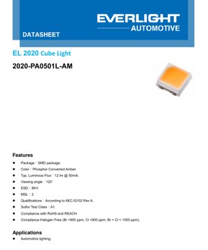
1. Product Overview
The 2020-PA0501L-AM is a surface-mount device (SMD) LED designed specifically for demanding automotive lighting applications. Its core offering is a reliable, Phosphor Converted Amber light source that meets stringent industry standards for performance and environmental resilience. The primary target market is automotive interior and exterior lighting systems where consistent color output, long-term reliability under harsh conditions, and compact form factor are critical requirements.
The LED's key advantages include its qualification according to the AEC-Q102 standard for discrete optoelectronic devices, ensuring it can withstand the rigorous thermal, mechanical, and environmental stresses of the automotive environment. It also boasts compliance with RoHS, REACH, and halogen-free directives, making it an environmentally conscious component choice. The typical luminous flux of 12 lumens at a drive current of 50mA provides sufficient brightness for various signaling and illumination functions.
2. In-Depth Technical Parameter Analysis
2.1 Photometric and Electrical Characteristics
The fundamental operating parameters are defined under specific test conditions, typically at a junction temperature (Tj) of 25°C and a forward current (IF) of 50mA. The Typical Luminous Flux (IV) is 12 lm, with a minimum of 8 lm and a maximum of 17 lm. This variation is addressed by the binning system detailed later. The Forward Voltage (VF) has a typical value of 3.0V, ranging from 2.50V to 3.50V. Designers must account for this voltage range when designing the driving circuitry to ensure consistent current regulation.
The Viewing Angle is specified as 120°, which describes the angular span where the luminous intensity is at least half of its peak value. This wide viewing angle is beneficial for applications requiring broad, even illumination rather than a highly focused beam.
2.2 Thermal and Absolute Maximum Ratings
Thermal management is crucial for LED longevity and performance stability. The datasheet provides two values for Thermal Resistance (Rth JS): a 'Real' value of 58 K/W (typ.) and an 'Electrical' value of 41 K/W (typ.). The 'Electrical' value, derived from the temperature coefficient of the forward voltage, is typically used for junction temperature estimation in practical applications. A lower thermal resistance indicates better heat dissipation from the LED junction to the solder point.
Absolute Maximum Ratings define the stress limits beyond which permanent damage may occur. Key limits include a maximum Forward Current (IF) of 120 mA, a maximum Junction Temperature (TJ) of 150°C, and an operating temperature range (Topr) from -40°C to +125°C. The device is rated for an ESD sensitivity (HBM) of 8 kV, which is important for handling and assembly processes. The maximum permissible Power Dissipation (Pd) is 420 mW.
3. Binning System Explanation
To ensure color and brightness consistency in production, LEDs are sorted into bins. This device uses three separate binning criteria.
3.1 Luminous Flux Bins
LEDs are categorized based on their measured light output at 50mA:
• Bin E4: 8 lm (Min) to 10 lm (Max)
• Bin E5: 10 lm (Min) to 13 lm (Max)
• Bin E6: 13 lm (Min) to 17 lm (Max)
The specific bin for a given production lot must be confirmed during ordering.
3.2 Forward Voltage Bins
LEDs are also binned by their forward voltage drop at the test current:
• Bin 2527: 2.50V (Min) to 2.75V (Max)
• Bin 2730: 2.75V (Min) to 3.00V (Max)
• Bin 3032: 3.00V (Min) to 3.25V (Max)
• Bin 3235: 3.25V (Min) to 3.50V (Max)
Selecting LEDs from a tight voltage bin can simplify driver design by reducing the range of supply voltage needed.
3.3 Color Binning Structure
The datasheet includes a chromaticity diagram (CIE 1931) showing the target color coordinates for Phosphor Converted Amber. Two primary bins, YA and YB, are defined with specific CIE x and CIE y coordinate boundaries. The typical dominant wavelength for this amber color is in the 590-595 nm range. The tight binning (tolerance ±0.005) ensures minimal color variation between different LEDs in an assembly, which is critical for automotive aesthetic and functional lighting.
4. Performance Curve Analysis
The graphs provide essential insights into the LED's behavior under varying conditions.
4.1 Spectral Distribution and Radiation Pattern
The Relative Spectral Distribution graph shows a single, broad peak characteristic of a phosphor-converted LED, with the primary emission in the amber/yellow region of the visible spectrum. The Typical Diagram Characteristics of Radiation illustrates the spatial intensity distribution, confirming the 120° viewing angle with a near-Lambertian pattern.
4.2 Electrical and Thermal Dependencies
The Forward Current vs. Forward Voltage (I-V Curve) shows the exponential relationship typical of a diode. The Relative Luminous Flux vs. Forward Current curve is sub-linear; increasing current yields diminishing returns in light output while generating more heat.
The Relative Luminous Flux vs. Junction Temperature graph is critical: light output decreases as the junction temperature increases. Effective heat sinking is necessary to maintain brightness. The Relative Forward Voltage vs. Junction Temperature curve has a negative coefficient, approximately -2 mV/°C, which can be used for temperature sensing.
The Forward Current Derating Curve dictates the maximum allowable continuous current based on the solder pad temperature. For example, at the maximum operating solder pad temperature of 125°C, the forward current must be reduced to 120 mA. The Permissible Pulse Handling Capability graph defines the peak current (IFM) the LED can handle for short pulse durations at various duty cycles, which is useful for PWM dimming or strobe applications.
5. Mechanical and Package Information
5.1 Mechanical Dimensions
The LED uses a standard "2020" package footprint, which typically refers to dimensions of approximately 2.0mm x 2.0mm. The exact mechanical drawing in the datasheet provides all critical dimensions including overall length, width, height, and the size/location of the thermal pad and electrical contacts. Tolerances are generally ±0.1mm unless otherwise specified.
5.2 Recommended Soldering Pad Layout
A land pattern design is provided for PCB layout. This includes the dimensions for the solder pads for the anode, cathode, and the central thermal pad. Following this recommended layout is essential for achieving reliable solder joints, proper thermal conduction to the PCB, and preventing tombstoning during reflow. The thermal pad is crucial for heat dissipation and must be properly connected to a copper pour on the PCB.
6. Soldering and Assembly Guidelines
6.1 Reflow Soldering Profile
The component is rated for a maximum soldering temperature of 260°C for 30 seconds. A standard lead-free reflow profile is applicable. Precautions must be taken to avoid excessive thermal shock. The Moisture Sensitivity Level (MSL) is rated at Level 2, meaning the device can be exposed to factory floor conditions for up to one year prior to soldering without requiring baking. If exceeded, baking according to IPC/JEDEC standards is necessary to prevent popcorning during reflow.
6.2 Precautions for Use
• Polarity: The device is not designed for reverse operation. Applying a reverse voltage can cause immediate damage.
• ESD Protection: Although rated at 8kV HBM, standard ESD handling procedures should be followed during assembly.
• Current Control: LEDs are current-driven devices. They must be operated with a constant current driver, not a constant voltage source, to prevent thermal runaway.
• Contamination: The device has a Sulfur Test Class A1 rating, indicating good resistance to sulfur-containing atmospheres, but exposure to other contaminants should still be minimized.
7. Packaging and Ordering Information
7.1 Part Number Decoding
The part number 2020-PA0501L-AM is structured as follows:
• 2020: Product family name (package size).
• PA: Color code for Phosphor Converted Amber.
• 50: Test current in milliamps (50 mA).
• 1: Lead Frame Type (1 = Gold-plated).
• L: Brightness Level (L = Low, relative to other bins in this series).
• AM: Designates Automotive application grade.
7.2 Packaging Specifications
The LEDs are supplied on tape and reel for automated assembly. The packaging information section would detail the reel dimensions, tape width, pocket spacing, and orientation of the components on the tape. This data is essential for programming pick-and-place machines.
8. Application Recommendations
8.1 Typical Application Scenarios
The primary application is Automotive Lighting. Specific uses include:
• Exterior: Turn signal indicators, side marker lights, daytime running lights (DRLs) in amber, center high-mount stop lights (CHMSL).
• Interior: Dashboard backlighting, switch illumination, ambient lighting, warning and indicator lights.
8.2 Design Considerations
• Thermal Management: The PCB should have adequate thermal vias under the thermal pad connected to internal ground planes or dedicated heat sinks to keep the junction temperature low, ensuring long life and stable light output.
• Optical Design: Lenses or light guides may be needed to shape the 120° beam for specific applications.
• Driver Selection: Choose an automotive-grade LED driver IC capable of supplying a stable 50mA (or as required) over the full automotive voltage range (e.g., 9V-16V with load dump protection). PWM dimming capability is often desirable.
• Series/Parallel Configuration: For driving multiple LEDs, a series connection is preferred as it ensures identical current through each unit, guaranteeing uniform brightness. Parallel connections require careful matching of forward voltage or individual current limiting.
9. Technical Comparison and Differentiation
Compared to standard commercial-grade LEDs, the 2020-PA0501L-AM's key differentiators are its AEC-Q102 qualification and extended operating temperature range (-40°C to +125°C). This makes it suitable for engine bay or exterior applications where temperature extremes are common. The Phosphor Converted Amber technology typically offers better color stability and consistency over time and temperature compared to older dyed-resin amber LEDs. The 8kV ESD rating and sulfur resistance provide additional robustness for harsh automotive environments.
10. Frequently Asked Questions (FAQs)
Q1: What is the difference between 'Real' and 'Electrical' thermal resistance?
A1: The 'Real' thermal resistance (Rth JS real) is measured using a physical temperature sensor. The 'Electrical' thermal resistance (Rth JS el) is calculated from the change in forward voltage with temperature, a method more practical for in-situ junction temperature estimation in a working circuit.
Q2: Can I drive this LED with a 3.3V power supply?
A2: Not directly. The LED requires current control. A simple resistor from a 3.3V supply is possible but inefficient and brightness will vary with the LED's forward voltage bin. A dedicated constant-current driver is strongly recommended for stable performance.
Q3: How do I interpret the binning codes when ordering?
A3: You must specify the required Luminous Flux Bin (e.g., E5), Forward Voltage Bin (e.g., 2730), and Color Bin (e.g., YA) based on your application's tolerance for variation. The manufacturer will supply parts meeting all three specified bin criteria.
Q4: Is this LED suitable for PWM dimming?
A4: Yes, LEDs are ideal for PWM dimming. The pulse handling capability graph should be consulted to ensure the peak current in the PWM waveform does not exceed the limits for the chosen pulse width and duty cycle.
11. Practical Design Case Study
Scenario: Designing an amber side marker light for a vehicle.
Requirements: Meet automotive EMI/EMC standards, operate from 9V-16V, survive temperature cycles, and maintain consistent color and brightness.
Implementation: A schematic would include an input filter, a buck-boost or linear LED driver IC rated for automotive use, set to deliver 50mA. Four 2020-PA0501L-AM LEDs would be connected in series to the driver output. The PCB would have a solid thermal pad area on the top layer under the LEDs, connected via multiple thermal vias to a large internal ground plane for heat spreading. The driver IC would include PWM dimming input connected to the vehicle's body control module. All components would be selected from AEC-Q qualified families.
12. Operational Principle
The 2020-PA0501L-AM is a solid-state light source based on a semiconductor chip, typically made of indium gallium nitride (InGaN) or similar materials, that emits blue light when forward biased. This blue light is absorbed by a layer of phosphor coating (the "Phosphor Converted" part) deposited directly on the chip. The phosphor re-emits light at longer wavelengths, primarily in the amber region. The combination of the remaining blue light and the broad-spectrum amber emission from the phosphor produces the final amber color perceived by the human eye. This method allows for precise control over the color point and high efficiency.
13. Technology Trends
The trend in automotive LED lighting is towards higher efficiency (more lumens per watt), higher power density, and improved reliability. This drives the development of new chip technologies, advanced phosphors with better thermal quenching resistance, and improved package designs with lower thermal resistance. There is also a move towards integrated modules that combine multiple LEDs, drivers, and optics into a single unit. Furthermore, the demand for smart, adaptive lighting systems is increasing, requiring LEDs that can be digitally controlled with high speed and precision. The underlying technology continues to evolve to provide better color rendering, longer lifetimes, and lower system costs for automotive manufacturers.
LED Specification Terminology
Complete explanation of LED technical terms
Photoelectric Performance
| Term | Unit/Representation | Simple Explanation | Why Important |
|---|---|---|---|
| Luminous Efficacy | lm/W (lumens per watt) | Light output per watt of electricity, higher means more energy efficient. | Directly determines energy efficiency grade and electricity cost. |
| Luminous Flux | lm (lumens) | Total light emitted by source, commonly called "brightness". | Determines if the light is bright enough. |
| Viewing Angle | ° (degrees), e.g., 120° | Angle where light intensity drops to half, determines beam width. | Affects illumination range and uniformity. |
| CCT (Color Temperature) | K (Kelvin), e.g., 2700K/6500K | Warmth/coolness of light, lower values yellowish/warm, higher whitish/cool. | Determines lighting atmosphere and suitable scenarios. |
| CRI / Ra | Unitless, 0–100 | Ability to render object colors accurately, Ra≥80 is good. | Affects color authenticity, used in high-demand places like malls, museums. |
| SDCM | MacAdam ellipse steps, e.g., "5-step" | Color consistency metric, smaller steps mean more consistent color. | Ensures uniform color across same batch of LEDs. |
| Dominant Wavelength | nm (nanometers), e.g., 620nm (red) | Wavelength corresponding to color of colored LEDs. | Determines hue of red, yellow, green monochrome LEDs. |
| Spectral Distribution | Wavelength vs intensity curve | Shows intensity distribution across wavelengths. | Affects color rendering and quality. |
Electrical Parameters
| Term | Symbol | Simple Explanation | Design Considerations |
|---|---|---|---|
| Forward Voltage | Vf | Minimum voltage to turn on LED, like "starting threshold". | Driver voltage must be ≥Vf, voltages add up for series LEDs. |
| Forward Current | If | Current value for normal LED operation. | Usually constant current drive, current determines brightness & lifespan. |
| Max Pulse Current | Ifp | Peak current tolerable for short periods, used for dimming or flashing. | Pulse width & duty cycle must be strictly controlled to avoid damage. |
| Reverse Voltage | Vr | Max reverse voltage LED can withstand, beyond may cause breakdown. | Circuit must prevent reverse connection or voltage spikes. |
| Thermal Resistance | Rth (°C/W) | Resistance to heat transfer from chip to solder, lower is better. | High thermal resistance requires stronger heat dissipation. |
| ESD Immunity | V (HBM), e.g., 1000V | Ability to withstand electrostatic discharge, higher means less vulnerable. | Anti-static measures needed in production, especially for sensitive LEDs. |
Thermal Management & Reliability
| Term | Key Metric | Simple Explanation | Impact |
|---|---|---|---|
| Junction Temperature | Tj (°C) | Actual operating temperature inside LED chip. | Every 10°C reduction may double lifespan; too high causes light decay, color shift. |
| Lumen Depreciation | L70 / L80 (hours) | Time for brightness to drop to 70% or 80% of initial. | Directly defines LED "service life". |
| Lumen Maintenance | % (e.g., 70%) | Percentage of brightness retained after time. | Indicates brightness retention over long-term use. |
| Color Shift | Δu′v′ or MacAdam ellipse | Degree of color change during use. | Affects color consistency in lighting scenes. |
| Thermal Aging | Material degradation | Deterioration due to long-term high temperature. | May cause brightness drop, color change, or open-circuit failure. |
Packaging & Materials
| Term | Common Types | Simple Explanation | Features & Applications |
|---|---|---|---|
| Package Type | EMC, PPA, Ceramic | Housing material protecting chip, providing optical/thermal interface. | EMC: good heat resistance, low cost; Ceramic: better heat dissipation, longer life. |
| Chip Structure | Front, Flip Chip | Chip electrode arrangement. | Flip chip: better heat dissipation, higher efficacy, for high-power. |
| Phosphor Coating | YAG, Silicate, Nitride | Covers blue chip, converts some to yellow/red, mixes to white. | Different phosphors affect efficacy, CCT, and CRI. |
| Lens/Optics | Flat, Microlens, TIR | Optical structure on surface controlling light distribution. | Determines viewing angle and light distribution curve. |
Quality Control & Binning
| Term | Binning Content | Simple Explanation | Purpose |
|---|---|---|---|
| Luminous Flux Bin | Code e.g., 2G, 2H | Grouped by brightness, each group has min/max lumen values. | Ensures uniform brightness in same batch. |
| Voltage Bin | Code e.g., 6W, 6X | Grouped by forward voltage range. | Facilitates driver matching, improves system efficiency. |
| Color Bin | 5-step MacAdam ellipse | Grouped by color coordinates, ensuring tight range. | Guarantees color consistency, avoids uneven color within fixture. |
| CCT Bin | 2700K, 3000K etc. | Grouped by CCT, each has corresponding coordinate range. | Meets different scene CCT requirements. |
Testing & Certification
| Term | Standard/Test | Simple Explanation | Significance |
|---|---|---|---|
| LM-80 | Lumen maintenance test | Long-term lighting at constant temperature, recording brightness decay. | Used to estimate LED life (with TM-21). |
| TM-21 | Life estimation standard | Estimates life under actual conditions based on LM-80 data. | Provides scientific life prediction. |
| IESNA | Illuminating Engineering Society | Covers optical, electrical, thermal test methods. | Industry-recognized test basis. |
| RoHS / REACH | Environmental certification | Ensures no harmful substances (lead, mercury). | Market access requirement internationally. |
| ENERGY STAR / DLC | Energy efficiency certification | Energy efficiency and performance certification for lighting. | Used in government procurement, subsidy programs, enhances competitiveness. |