Table of Contents
- 1. Product Overview
- 1.1 Core Advantages and Target Market
- 2. Technical Parameter Deep Dive
- 2.1 Absolute Maximum Ratings
- 2.2 Electro-Optical Characteristics
- 2.3 Thermal Considerations
- 3. Binning System Explanation
- 3.1 Luminous Intensity Binning
- 3.2 Dominant Wavelength Binning
- 3.3 Forward Voltage Binning
- 4. Performance Curve Analysis
- 4.1 Relative Intensity vs. Wavelength
- 4.2 Directivity Pattern
- 4.3 Forward Current vs. Forward Voltage (I-V Curve)
- 4.4 Relative Intensity vs. Forward Current
- 4.5 Temperature Dependence Curves
- 5. Mechanical and Package Information
- 5.1 Package Dimensions
- 5.2 Polarity Identification
- 6. Soldering and Assembly Guidelines
- 6.1 Lead Forming
- 6.2 Soldering Process
- 6.3 Storage Conditions
- 7. Packaging and Ordering Information
- 7.1 Packing Specification
- 7.2 Label Explanation
- 7.3 Production Designation / Model Number
- 8. Application Suggestions and Design Considerations
- 8.1 Typical Application Scenarios
- 8.2 Design Considerations
- 9. Technical Comparison and Differentiation
- 10. Frequently Asked Questions (Based on Technical Parameters)
- 11. Practical Design and Usage Case
- 12. Technology Principle Introduction
- 13. Technology Development Trends
- LED Specification Terminology
- Photoelectric Performance
- Electrical Parameters
- Thermal Management & Reliability
- Packaging & Materials
- Quality Control & Binning
- Testing & Certification
1. Product Overview
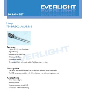
This document details the specifications for a high-brightness LED lamp designed for applications requiring superior luminous output. The device utilizes AlGaInP chip technology to produce a brilliant red color and is encapsulated in a UV-resistant, water-clear epoxy resin within a popular T-1 3/4 round package. Its design prioritizes reliability, robustness, and efficiency, making it suitable for demanding outdoor and commercial applications. The product is compliant with relevant environmental regulations and is available in tape and reel packaging for automated assembly processes.
1.1 Core Advantages and Target Market
The primary advantage of this LED series is its high luminous intensity, which is achieved through optimized chip design and materials. The use of UV-resistant epoxy ensures long-term reliability and color stability when exposed to sunlight, a critical factor for outdoor use. The robust package design contributes to overall durability. This LED is specifically targeted at applications such as full-color graphic signs, message boards, variable message signs (VMS), and commercial outdoor advertising displays, where high visibility and consistent color performance are paramount.
2. Technical Parameter Deep Dive
This section provides a detailed, objective analysis of the device's key technical parameters as defined under standard test conditions (Ta=25°C).
2.1 Absolute Maximum Ratings
The Absolute Maximum Ratings define the stress limits beyond which permanent damage to the device may occur. These are not intended for normal operation. Key limits include a maximum reverse voltage (VR) of 5V, a continuous forward current (IF) of 50mA, and a peak forward current (IFP) of 160mA under pulsed conditions (1/10 duty cycle @1kHz). The maximum power dissipation (Pd) is 115mW. The device is rated for an operating temperature range of -40°C to +85°C and can withstand storage temperatures from -40°C to +100°C. It offers Electrostatic Discharge (ESD) protection up to 2000V (Human Body Model) and can endure a soldering temperature of 260°C for up to 5 seconds.
2.2 Electro-Optical Characteristics
The electro-optical characteristics define the device's performance under typical operating conditions (IF=20mA). The luminous intensity (Iv) has a typical value of 7150 millicandelas (mcd), with a minimum of 5650 mcd and a maximum of 11250 mcd. The viewing angle (2θ1/2) is typically 23 degrees, indicating a relatively focused beam. The peak wavelength (λp) is 632 nm, while the dominant wavelength (λd) is typically 624 nm, defining the perceived brilliant red color. The spectral bandwidth (Δλ) is 20 nm. The forward voltage (VF) is typically 2.0V, with a range from 1.8V to 2.6V. The reverse current (IR) is specified at a maximum of 10 μA when a 5V reverse bias is applied.
2.3 Thermal Considerations
While not explicitly detailed in a separate thermal resistance parameter, the maximum power dissipation of 115mW and the operating temperature range provide the primary thermal constraints. Designers must ensure that the junction temperature does not exceed its maximum limit by providing adequate heat sinking or limiting the operating current, especially in high ambient temperature environments. The performance curves show the relationship between relative luminous intensity and ambient temperature, which is crucial for predicting light output under varying thermal conditions.
3. Binning System Explanation
To ensure consistency in mass production, LEDs are sorted into bins based on key performance parameters. This allows designers to select parts that meet specific application requirements for brightness and color.
3.1 Luminous Intensity Binning
The luminous intensity is categorized into three bins: S (5650-7150 mcd), T (7150-9000 mcd), and U (9000-11250 mcd). All measurements are taken at IF=20mA. A tolerance of ±10% is applied within each bin. This binning allows for selection based on the required brightness level for a given application.
3.2 Dominant Wavelength Binning
The dominant wavelength, which defines the perceived color, is binned into two groups: Bin 1 (620-624 nm) and Bin 2 (624-628 nm). The tolerance for dominant wavelength is very tight at ±1 nm, ensuring excellent color consistency within a selected bin, which is critical for applications like full-color displays where color matching is essential.
3.3 Forward Voltage Binning
The forward voltage is divided into four bins: 1 (1.8-2.0V), 2 (2.0-2.2V), 3 (2.2-2.4V), and 4 (2.4-2.6V). Knowing the voltage bin is important for designing the driving circuitry, particularly for constant-current drivers, to ensure proper voltage headroom and efficiency. The note regarding \"Tolerance of Dominant Wavelength\" in this section appears to be a documentation error and should refer to forward voltage tolerance.
4. Performance Curve Analysis
Graphical data provides deeper insight into the device's behavior under non-standard conditions.
4.1 Relative Intensity vs. Wavelength
This curve plots the spectral power distribution, showing a peak at approximately 632 nm with a typical full width at half maximum (FWHM) of 20 nm. The narrow bandwidth is characteristic of AlGaInP-based red LEDs, resulting in a saturated color.
4.2 Directivity Pattern
The polar diagram illustrates the spatial distribution of light intensity. The typical 23-degree viewing angle (half-intensity angle) is confirmed, showing the intensity dropping to 50% of its on-axis value at approximately ±11.5 degrees from the center.
4.3 Forward Current vs. Forward Voltage (I-V Curve)
This curve shows the exponential relationship between forward current and forward voltage, typical of a diode. It is essential for determining the required drive voltage for a given operating current and for understanding the dynamic resistance of the LED.
4.4 Relative Intensity vs. Forward Current
This graph demonstrates how light output increases with drive current. It is generally linear within the recommended operating range but will eventually saturate and can lead to efficiency droop and accelerated degradation at excessively high currents.
4.5 Temperature Dependence Curves
Two key graphs show the impact of ambient temperature: Relative Intensity vs. Ambient Temperature typically shows a decrease in light output as temperature increases due to non-radiative recombination and other effects. Forward Current vs. Ambient Temperature (at constant voltage) would show an increase in current due to the negative temperature coefficient of the diode's forward voltage. These are critical for designing systems that operate reliably across the specified temperature range.
5. Mechanical and Package Information
5.1 Package Dimensions
The LED is housed in a standard T-1 3/4 (5mm) round package. The dimensional drawing specifies key measurements including the overall diameter, lead spacing, and epoxy lens geometry. A critical note specifies that the protruded resin under the flange has a maximum height of 1.5mm, which must be considered for PCB layout and clearance. All unspecified dimensions have a tolerance of ±0.25mm.
5.2 Polarity Identification
The cathode is typically identified by a flat spot on the rim of the LED package or by the shorter lead. The datasheet diagram should be consulted for the specific polarity marking used on this device to ensure correct orientation during assembly.
6. Soldering and Assembly Guidelines
Proper handling is crucial to maintain LED performance and reliability.
6.1 Lead Forming
If leads need to be bent, it must be done at a point at least 3mm from the base of the epoxy bulb to prevent stress on the internal die and wire bonds. Forming must be performed before soldering, at room temperature, and with care to avoid applying stress to the package. PCB hole alignment must be precise to avoid mounting stress.
6.2 Soldering Process
Two soldering methods are addressed:
Hand Soldering: Iron tip temperature should not exceed 300°C (for a max 30W iron), and soldering time per lead should be 3 seconds maximum. The solder joint must be at least 3mm from the epoxy bulb.
Wave/Dip Soldering: Preheating should not exceed 100°C for 60 seconds maximum. The solder bath temperature should be a maximum of 260°C for 5 seconds. Again, a 3mm minimum distance from the epoxy bulb must be maintained.
A recommended soldering temperature profile is provided, emphasizing the importance of controlled heating and cooling rates to prevent thermal shock. Soldering (dip or hand) should not be performed more than once. The LED must be protected from mechanical shock until it returns to room temperature after soldering.
6.3 Storage Conditions
LEDs should be stored at 30°C or less and 70% Relative Humidity or less. The recommended storage life after shipment is 3 months. For longer storage (up to one year), they should be kept in a sealed container with a nitrogen atmosphere and moisture-absorbent material. Rapid temperature changes in high humidity environments should be avoided to prevent condensation.
7. Packaging and Ordering Information
7.1 Packing Specification
The LEDs are packaged in anti-static bags to protect against electrostatic discharge. The packing hierarchy is: 200 to 500 pieces per bag, 5 bags per inner carton, and 10 inner cartons per outside carton. The packing materials are moisture-resistant.
7.2 Label Explanation
The product label contains several codes: CPN (Customer's Product Number), P/N (Product Number), QTY (Packing Quantity), CAT (ranks for Luminous Intensity and Forward Voltage), HUE (rank for Dominant Wavelength), REF (Reference), and LOT No (Lot Number for traceability).
7.3 Production Designation / Model Number
The part number 7343/R5C2-ASUB/MS follows a structured format. The \"7343\" likely refers to the series or package type. \"R5\" indicates the color (Brilliant Red) and luminous intensity bin. \"C2\" specifies the dominant wavelength bin. The \"ASUB/MS\" suffix may denote special features, lens type, or packaging (e.g., tape and reel). The exact decoding of each segment should be cross-referenced with the manufacturer's full product guide.
8. Application Suggestions and Design Considerations
8.1 Typical Application Scenarios
This high-brightness red LED is ideally suited for:
• Color Graphic Signs & Message Boards: As a primary red element in RGB pixel clusters.
• Variable Message Signs (VMS): For traffic information displays requiring long-distance visibility and all-weather reliability.
• Commercial Outdoor Advertising: In large-format displays where high luminous intensity ensures visibility in bright ambient light.
8.2 Design Considerations
• Current Driving: Always use a constant-current driver to ensure stable light output and prevent thermal runaway. The typical operating point is 20mA, but the circuit should be designed to respect the absolute maximum of 50mA continuous current.
• Thermal Management: For applications operating at high ambient temperatures or at high drive currents, consider the thermal path from the LED leads to the PCB copper and/or an external heatsink to maintain junction temperature within limits.
• Optics: The 23-degree viewing angle provides a focused beam. For wider illumination, secondary optics (diffusers, lenses) may be required.
• ESD Protection: Although the device has 2000V HBM ESD protection, implementing standard ESD handling procedures during assembly is still recommended.
9. Technical Comparison and Differentiation
Compared to standard indicator-grade red LEDs, this device offers significantly higher luminous intensity (multi-thousand mcd vs. hundreds of mcd), making it unsuitable for simple status indication but ideal for illumination and signage. The use of AlGaInP semiconductor material, as opposed to older GaAsP or GaP technologies, provides higher efficiency and a more vibrant, saturated red color. The tight binning on wavelength (±1 nm) and intensity offers superior color and brightness uniformity compared to broadly binned parts, which is a critical advantage in multi-LED array applications like displays.
10. Frequently Asked Questions (Based on Technical Parameters)
Q: Can I drive this LED at 50mA continuously?
A: While 50mA is the absolute maximum continuous rating, the typical electro-optical characteristics are specified at 20mA. Operating at 50mA will produce higher light output but will also generate more heat, reduce efficiency (efficiency droop), and potentially shorten lifespan. It is advisable to design for a lower current like 20mA for optimal reliability and efficiency.
Q: What is the difference between peak wavelength (632 nm) and dominant wavelength (624 nm typical)?
A: Peak wavelength is the wavelength at which the spectral power output is maximum. Dominant wavelength is the single wavelength of monochromatic light that matches the perceived color of the LED. Due to the shape of the human eye's photopic response curve, the dominant wavelength for a red LED is often slightly shorter (shifted towards yellow) than the peak wavelength.
Q: How do I select the correct bin for my application?
A: For color-critical applications (e.g., RGB displays), select a tight dominant wavelength bin (e.g., Bin 1 or 2) and use the same bin across all red LEDs. For brightness-critical applications where color variation is less important, you might select a higher luminous intensity bin (U or T). The forward voltage bin is mainly important for ensuring your driver circuit has sufficient voltage headroom for the entire batch.
11. Practical Design and Usage Case
Case: Designing a High-Visibility Outdoor Warning Sign.
A designer is creating a compact, solar-powered warning sign that must be visible from 100 meters in daylight. They select this LED for the red \"STOP\" message. They choose LEDs from the U bin (9000-11250 mcd) for maximum brightness and Bin 1 for dominant wavelength (620-624 nm) to ensure a consistent red hue. They design a constant-current driver set to 20mA per LED. The PCB layout ensures a minimum 3mm clearance between the solder pad and the LED body, and the copper pour around the leads is maximized to act as a heatsink. During assembly, they follow the wave soldering profile precisely and implement ESD-safe handling practices. The result is a sign with excellent, uniform brightness and long-term reliability under varying outdoor temperatures.
12. Technology Principle Introduction
This LED is based on an AlGaInP (Aluminum Gallium Indium Phosphide) semiconductor chip. When a forward voltage is applied, electrons and holes are injected into the active region of the semiconductor where they recombine. In a direct bandgap material like AlGaInP, this recombination releases energy in the form of photons (light). The specific wavelength of the emitted light (red, in this case) is determined by the bandgap energy of the semiconductor material, which is engineered by adjusting the ratios of aluminum, gallium, and indium. The water-clear epoxy lens serves to protect the chip, shape the light output beam, and enhance light extraction from the semiconductor.
13. Technology Development Trends
The general trend in LED technology for signage and illumination is towards ever-higher luminous efficacy (lumens per watt), improved color rendering, and lower cost. For AlGaInP-based red LEDs, research continues to push the external quantum efficiency by improving light extraction from the chip and reducing internal losses. There is also ongoing development in phosphor-converted LEDs that use a blue or violet pump LED with a red phosphor, which can offer different spectral and efficiency characteristics. Furthermore, miniaturization and increased power density in packages, along with enhanced reliability for harsh environments, remain key focus areas for components used in outdoor and automotive applications.
LED Specification Terminology
Complete explanation of LED technical terms
Photoelectric Performance
| Term | Unit/Representation | Simple Explanation | Why Important |
|---|---|---|---|
| Luminous Efficacy | lm/W (lumens per watt) | Light output per watt of electricity, higher means more energy efficient. | Directly determines energy efficiency grade and electricity cost. |
| Luminous Flux | lm (lumens) | Total light emitted by source, commonly called "brightness". | Determines if the light is bright enough. |
| Viewing Angle | ° (degrees), e.g., 120° | Angle where light intensity drops to half, determines beam width. | Affects illumination range and uniformity. |
| CCT (Color Temperature) | K (Kelvin), e.g., 2700K/6500K | Warmth/coolness of light, lower values yellowish/warm, higher whitish/cool. | Determines lighting atmosphere and suitable scenarios. |
| CRI / Ra | Unitless, 0–100 | Ability to render object colors accurately, Ra≥80 is good. | Affects color authenticity, used in high-demand places like malls, museums. |
| SDCM | MacAdam ellipse steps, e.g., "5-step" | Color consistency metric, smaller steps mean more consistent color. | Ensures uniform color across same batch of LEDs. |
| Dominant Wavelength | nm (nanometers), e.g., 620nm (red) | Wavelength corresponding to color of colored LEDs. | Determines hue of red, yellow, green monochrome LEDs. |
| Spectral Distribution | Wavelength vs intensity curve | Shows intensity distribution across wavelengths. | Affects color rendering and quality. |
Electrical Parameters
| Term | Symbol | Simple Explanation | Design Considerations |
|---|---|---|---|
| Forward Voltage | Vf | Minimum voltage to turn on LED, like "starting threshold". | Driver voltage must be ≥Vf, voltages add up for series LEDs. |
| Forward Current | If | Current value for normal LED operation. | Usually constant current drive, current determines brightness & lifespan. |
| Max Pulse Current | Ifp | Peak current tolerable for short periods, used for dimming or flashing. | Pulse width & duty cycle must be strictly controlled to avoid damage. |
| Reverse Voltage | Vr | Max reverse voltage LED can withstand, beyond may cause breakdown. | Circuit must prevent reverse connection or voltage spikes. |
| Thermal Resistance | Rth (°C/W) | Resistance to heat transfer from chip to solder, lower is better. | High thermal resistance requires stronger heat dissipation. |
| ESD Immunity | V (HBM), e.g., 1000V | Ability to withstand electrostatic discharge, higher means less vulnerable. | Anti-static measures needed in production, especially for sensitive LEDs. |
Thermal Management & Reliability
| Term | Key Metric | Simple Explanation | Impact |
|---|---|---|---|
| Junction Temperature | Tj (°C) | Actual operating temperature inside LED chip. | Every 10°C reduction may double lifespan; too high causes light decay, color shift. |
| Lumen Depreciation | L70 / L80 (hours) | Time for brightness to drop to 70% or 80% of initial. | Directly defines LED "service life". |
| Lumen Maintenance | % (e.g., 70%) | Percentage of brightness retained after time. | Indicates brightness retention over long-term use. |
| Color Shift | Δu′v′ or MacAdam ellipse | Degree of color change during use. | Affects color consistency in lighting scenes. |
| Thermal Aging | Material degradation | Deterioration due to long-term high temperature. | May cause brightness drop, color change, or open-circuit failure. |
Packaging & Materials
| Term | Common Types | Simple Explanation | Features & Applications |
|---|---|---|---|
| Package Type | EMC, PPA, Ceramic | Housing material protecting chip, providing optical/thermal interface. | EMC: good heat resistance, low cost; Ceramic: better heat dissipation, longer life. |
| Chip Structure | Front, Flip Chip | Chip electrode arrangement. | Flip chip: better heat dissipation, higher efficacy, for high-power. |
| Phosphor Coating | YAG, Silicate, Nitride | Covers blue chip, converts some to yellow/red, mixes to white. | Different phosphors affect efficacy, CCT, and CRI. |
| Lens/Optics | Flat, Microlens, TIR | Optical structure on surface controlling light distribution. | Determines viewing angle and light distribution curve. |
Quality Control & Binning
| Term | Binning Content | Simple Explanation | Purpose |
|---|---|---|---|
| Luminous Flux Bin | Code e.g., 2G, 2H | Grouped by brightness, each group has min/max lumen values. | Ensures uniform brightness in same batch. |
| Voltage Bin | Code e.g., 6W, 6X | Grouped by forward voltage range. | Facilitates driver matching, improves system efficiency. |
| Color Bin | 5-step MacAdam ellipse | Grouped by color coordinates, ensuring tight range. | Guarantees color consistency, avoids uneven color within fixture. |
| CCT Bin | 2700K, 3000K etc. | Grouped by CCT, each has corresponding coordinate range. | Meets different scene CCT requirements. |
Testing & Certification
| Term | Standard/Test | Simple Explanation | Significance |
|---|---|---|---|
| LM-80 | Lumen maintenance test | Long-term lighting at constant temperature, recording brightness decay. | Used to estimate LED life (with TM-21). |
| TM-21 | Life estimation standard | Estimates life under actual conditions based on LM-80 data. | Provides scientific life prediction. |
| IESNA | Illuminating Engineering Society | Covers optical, electrical, thermal test methods. | Industry-recognized test basis. |
| RoHS / REACH | Environmental certification | Ensures no harmful substances (lead, mercury). | Market access requirement internationally. |
| ENERGY STAR / DLC | Energy efficiency certification | Energy efficiency and performance certification for lighting. | Used in government procurement, subsidy programs, enhances competitiveness. |