Table of Contents
- 1. Product Overview
- 1.1 Core Advantages and Target Market
- 2. In-Depth Technical Parameter Analysis
- 2.1 Absolute Maximum Ratings
- 2.2 Electro-Optical Characteristics
- 2.2.1 Input Characteristics (LED Side)
- 2.2.2 Output Characteristics (Phototransistor Side)
- 2.2.3 Transfer Characteristics
- 3. Performance Curve Analysis
- 4. Mechanical and Package Information
- 4.1 Package Dimensions and Pin Configuration
- 4.2 Device Marking
- 5. Soldering and Assembly Guidelines
- 5.1 Reflow Soldering Conditions
- 6. Packaging and Ordering Information
- 6.1 Ordering Part Number System
- 6.2 Tape and Reel Specifications
- 7. Application Recommendations
- 7.1 Typical Application Circuits
- 7.2 Design Considerations and Precautions
- 8. Technical Comparison and Differentiation
- 9. Frequently Asked Questions (FAQ)
- 10. Practical Design Case Study
- 11. Operating Principle
- 12. Industry Trends and Developments
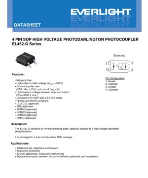
1. Product Overview
The EL452-G series is a high-voltage photodarlington optocoupler designed for reliable signal transmission between circuits of different potentials. It integrates an infrared emitting diode optically coupled to a high-voltage darlington phototransistor. The device is housed in a compact 4-pin Small Outline Package (SOP) with a low 2.0mm profile, making it suitable for space-constrained surface-mount applications. Its primary function is to provide electrical isolation while transmitting control or data signals, protecting sensitive circuitry from high voltage transients and ground loop issues.
1.1 Core Advantages and Target Market
The key advantages of this component include its high collector-emitter voltage rating of 350V (VCEO), which is essential for interfacing with mains-powered circuits or motor drives. It offers a very high current transfer ratio (CTR) with a minimum of 1000% at standard test conditions, ensuring strong output signal levels from a modest input current. The device boasts a high isolation voltage of 3750Vrms between its input and output sides, meeting stringent safety standards. It is also halogen-free and compliant with RoHS and Pb-free directives. These features make it ideal for applications in telecommunications equipment (telephone sets, exchanges), industrial sequence controllers, system appliances, measuring instruments, and any scenario requiring safe signal transmission across different voltage domains.
2. In-Depth Technical Parameter Analysis
This section provides a detailed, objective interpretation of the device's electrical, optical, and thermal specifications as defined in its absolute maximum ratings and electro-optical characteristics.
2.1 Absolute Maximum Ratings
The absolute maximum ratings define the stress limits beyond which permanent damage to the device may occur. The input forward current (IF) is rated at 60mA continuous, with a short-duration peak forward current (IFM) of 1A for 10µs. The total power dissipation (PTOT) must not exceed 170mW. The critical output parameter is the collector-emitter voltage (VCEO) of 350V, which is the maximum voltage the output transistor can block when the input LED is off. The isolation voltage (VISO) of 3750Vrms for one minute specifies the dielectric strength of the internal insulation barrier. The device operates within a temperature range of -55°C to +110°C.
2.2 Electro-Optical Characteristics
The electro-optical characteristics define the device's performance under normal operating conditions at 25°C.
2.2.1 Input Characteristics (LED Side)
The forward voltage (VF) of the infrared LED is typically 1.2V with a maximum of 1.4V at a forward current of 10mA. This low VF contributes to lower power consumption on the input side. The reverse leakage current (IR) is a maximum of 10µA at 4V reverse bias.
2.2.2 Output Characteristics (Phototransistor Side)
The collector-emitter dark current (ICEO), which is the leakage current when the LED is off, is specified at a maximum of 100nA at VCE=200V. The collector-emitter breakdown voltage (BVCEO) is a minimum of 350V, confirming the high-voltage capability. The collector-emitter saturation voltage (VCE(sat)) is typically 1.2V (max 1.5V) when the device is fully on (IF=20mA, IC=100mA), indicating the voltage drop across the output in the conducting state.
2.2.3 Transfer Characteristics
The Current Transfer Ratio (CTR) is the most critical parameter, defined as the ratio of output collector current to input forward current, expressed as a percentage. For the EL452-G, the CTR is a minimum of 1000%, typically 2000%, at IF=1mA and VCE=2V. This exceptionally high CTR is characteristic of a darlington configuration, which provides high current gain, allowing small input currents to control larger output currents effectively. The switching speed is characterized by rise time (tr) of typically 80µs (max 250µs) and fall time (tf) of typically 10µs (max 100µs). These times are relatively slow due to the darlington structure and the inherent charge storage in phototransistors, making the device suitable for low-to-moderate frequency switching and linear analog applications, but not for high-speed digital isolation. The cut-off frequency (fc) is typically 7kHz. The isolation resistance (RIO) is a minimum of 5×10¹⁰ Ω, indicating excellent DC isolation.
3. Performance Curve Analysis
While the PDF indicates the presence of typical electro-optical characteristic curves, the specific graphs (e.g., CTR vs. Forward Current, CTR vs. Temperature, Collector Current vs. Collector-Emitter Voltage) are not provided in the text content. In a full datasheet, these curves are crucial for design. They typically show how CTR degrades with increasing temperature, how output current saturates at high input currents or low collector-emitter voltages, and the relationship between forward voltage and current for the LED. Designers must consult these graphs to understand device behavior across the full operating range, not just at the 25°C typical point.
4. Mechanical and Package Information
4.1 Package Dimensions and Pin Configuration
The device uses a 4-pin SOP package. The package body dimensions are approximately 4.4mm in length and 7.4mm in width, with a height profile of 2.0mm. The pin configuration is standard for such optocouplers: Pin 1 is the LED Anode, Pin 2 is the LED Cathode, Pin 3 is the Phototransistor Emitter, and Pin 4 is the Phototransistor Collector. A recommended pad layout for surface mounting is provided to ensure reliable soldering and mechanical stability.
4.2 Device Marking
The device is marked on the top surface with a code. The marking includes "EL" (manufacturer code), "452" (part number), a one-digit year code, a two-digit week code, and an optional "V" to denote VDE approval. This marking allows for traceability of manufacturing date and compliance.
5. Soldering and Assembly Guidelines
5.1 Reflow Soldering Conditions
The datasheet provides detailed reflow soldering profile specifications to prevent thermal damage. The profile is compliant with IPC/JEDEC J-STD-020D. Key parameters include: a preheat stage from 150°C to 200°C over 60-120 seconds, a peak body temperature (Tp) not exceeding 260°C, and a time above liquidus (217°C) between 60-100 seconds. The device can withstand a maximum of three reflow cycles. Adherence to this profile is critical to maintain the integrity of the internal epoxy encapsulation and the wire bonds.
6. Packaging and Ordering Information
6.1 Ordering Part Number System
The part number follows the format: EL452(Y)-VG. The "Y" position indicates the tape and reel option (TA, TB, or none for tube packaging). The "V" denotes that the unit is VDE safety approved. The "G" suffix indicates the product is halogen-free. For example, EL452TA-VG refers to the device supplied on TA orientation tape and reel, with VDE approval, and is halogen-free.
6.2 Tape and Reel Specifications
The device is available in standard embossed carrier tape for automated assembly. Two feed directions are available: Option TA and Option TB. The tape width (W) is 16.0mm, the pocket pitch (P0) is 4.0mm, and the reel typically holds 3000 units. Detailed tape dimensions (A, B, D0, etc.) are provided for feeder setup.
7. Application Recommendations
7.1 Typical Application Circuits
The EL452-G is well-suited for driving triacs, thyristors, or MOSFETs in AC mains control circuits (e.g., solid-state relays) due to its high VCEO. It can be used for voltage level shifting in microcontroller interfaces, providing isolation for analog sensor signals, and creating isolated feedback loops in switch-mode power supplies. Its high CTR allows it to be driven directly from microcontroller GPIO pins (with a suitable current-limiting resistor) without needing an additional driver transistor for the LED.
7.2 Design Considerations and Precautions
Input Side: A series resistor must always be used with the LED to limit the forward current to a safe value, typically between 1mA and 20mA depending on the required CTR and speed. The LED is sensitive to reverse voltage; if the driving circuit can impose a reverse bias, a protection diode in parallel with the LED is recommended.
Output Side: The photodarlington can sink significant current (up to 150mA). A load resistor must be connected between the collector and the positive supply rail to set the output voltage swing and limit power dissipation. Due to the darlington configuration, the saturation voltage (VCE(sat)) is higher than for a single transistor, which reduces the output voltage swing in switching applications. Designers must account for the CTR degradation over temperature and lifetime; a design margin of 20-50% is advisable. The relatively slow switching speeds preclude its use in high-frequency PWM or data communication above a few kilohertz.
8. Technical Comparison and Differentiation
The EL452-G differentiates itself in the market through its combination of high voltage (350V), very high CTR (1000% min), and compact SOP package. Compared to standard phototransistor couplers (which may have CTRs of 50-600%), the darlington configuration provides much higher sensitivity. Compared to some other photodarlingtons, its 3750Vrms isolation rating and multiple international safety approvals (UL, CUL, VDE, SEMKO, etc.) make it a robust choice for safety-critical and industrial applications. The halogen-free and RoHS compliance aligns with modern environmental regulations.
9. Frequently Asked Questions (FAQ)
Q: Can I drive the LED directly from a 5V logic output?
A: Yes, but you must calculate the series resistor. For example, with a typical VF of 1.2V and a desired IF of 5mA from a 5V supply: R = (5V - 1.2V) / 0.005A = 760Ω. Use a standard 750Ω resistor.
Q: What is the maximum switching frequency?
A: The practical switching frequency is limited by the rise and fall times. A conservative estimate for a square wave is 1/(tr+tf) ≈ 1/(250µs+100µs) ≈ 2.9kHz. For reliable operation, design for frequencies below 1kHz.
Q: How does temperature affect performance?
A: CTR typically decreases with increasing temperature. The dark current (ICEO) increases with temperature. The forward voltage of the LED decreases with temperature. These effects must be considered for stable operation over the full temperature range.
Q: Is an external base connection available for speed-up?
A: No. This is a standard photodarlington with no external base lead. Switching speed cannot be improved by external components.
10. Practical Design Case Study
Scenario: Isolating a 3.3V microcontroller signal to control a 24V DC relay coil.
Implementation: The microcontroller GPIO pin (3.3V) drives the LED via a 470Ω resistor, setting IF ≈ (3.3V - 1.2V)/470Ω ≈ 4.5mA. The relay coil (24V, 50Ω coil ≈ 480mA) is connected between a 24V supply and the collector of the EL452-G. The emitter is connected to ground. A flyback diode must be placed across the relay coil to suppress voltage spikes when the photodarlington turns off. At 4.5mA input, the CTR ensures a saturated output capable of sinking the relay current, with VCE(sat) causing a small voltage drop. The 350V VCEO provides ample margin against the 24V supply and any inductive spikes.
11. Operating Principle
The device operates on the principle of optical coupling. When current flows through the input infrared Light Emitting Diode (LED), it emits photons. These photons travel across a transparent insulating gap and strike the base region of the output darlington phototransistor pair. The absorbed photons generate electron-hole pairs, creating a base current that turns on the darlington transistor pair. This allows a much larger current to flow from the collector to the emitter, proportional to the LED current (defined by the CTR). The key is that the signal is transmitted by light, providing complete galvanic isolation between the input and output circuits, as there is no electrical connection—only an optical path through an insulating material.
12. Industry Trends and Developments
The optocoupler market continues to evolve. Trends include the development of higher-speed digital isolators based on CMOS and RF technology, which offer superior speed, power consumption, and noise immunity compared to traditional optocouplers. However, photodarlington and phototransistor optocouplers like the EL452-G retain strong positions in applications requiring high voltage capability, high current output, simplicity, robustness, and cost-effectiveness for low-to-medium frequency isolation. There is also a continuous push for miniaturization, higher integration (e.g., combining multiple channels), improved reliability, and enhanced safety certifications to meet evolving global standards. The move towards halogen-free and environmentally friendly materials, as seen in the EL452-G, is a standard industry requirement.
LED Specification Terminology
Complete explanation of LED technical terms
Photoelectric Performance
| Term | Unit/Representation | Simple Explanation | Why Important |
|---|---|---|---|
| Luminous Efficacy | lm/W (lumens per watt) | Light output per watt of electricity, higher means more energy efficient. | Directly determines energy efficiency grade and electricity cost. |
| Luminous Flux | lm (lumens) | Total light emitted by source, commonly called "brightness". | Determines if the light is bright enough. |
| Viewing Angle | ° (degrees), e.g., 120° | Angle where light intensity drops to half, determines beam width. | Affects illumination range and uniformity. |
| CCT (Color Temperature) | K (Kelvin), e.g., 2700K/6500K | Warmth/coolness of light, lower values yellowish/warm, higher whitish/cool. | Determines lighting atmosphere and suitable scenarios. |
| CRI / Ra | Unitless, 0–100 | Ability to render object colors accurately, Ra≥80 is good. | Affects color authenticity, used in high-demand places like malls, museums. |
| SDCM | MacAdam ellipse steps, e.g., "5-step" | Color consistency metric, smaller steps mean more consistent color. | Ensures uniform color across same batch of LEDs. |
| Dominant Wavelength | nm (nanometers), e.g., 620nm (red) | Wavelength corresponding to color of colored LEDs. | Determines hue of red, yellow, green monochrome LEDs. |
| Spectral Distribution | Wavelength vs intensity curve | Shows intensity distribution across wavelengths. | Affects color rendering and quality. |
Electrical Parameters
| Term | Symbol | Simple Explanation | Design Considerations |
|---|---|---|---|
| Forward Voltage | Vf | Minimum voltage to turn on LED, like "starting threshold". | Driver voltage must be ≥Vf, voltages add up for series LEDs. |
| Forward Current | If | Current value for normal LED operation. | Usually constant current drive, current determines brightness & lifespan. |
| Max Pulse Current | Ifp | Peak current tolerable for short periods, used for dimming or flashing. | Pulse width & duty cycle must be strictly controlled to avoid damage. |
| Reverse Voltage | Vr | Max reverse voltage LED can withstand, beyond may cause breakdown. | Circuit must prevent reverse connection or voltage spikes. |
| Thermal Resistance | Rth (°C/W) | Resistance to heat transfer from chip to solder, lower is better. | High thermal resistance requires stronger heat dissipation. |
| ESD Immunity | V (HBM), e.g., 1000V | Ability to withstand electrostatic discharge, higher means less vulnerable. | Anti-static measures needed in production, especially for sensitive LEDs. |
Thermal Management & Reliability
| Term | Key Metric | Simple Explanation | Impact |
|---|---|---|---|
| Junction Temperature | Tj (°C) | Actual operating temperature inside LED chip. | Every 10°C reduction may double lifespan; too high causes light decay, color shift. |
| Lumen Depreciation | L70 / L80 (hours) | Time for brightness to drop to 70% or 80% of initial. | Directly defines LED "service life". |
| Lumen Maintenance | % (e.g., 70%) | Percentage of brightness retained after time. | Indicates brightness retention over long-term use. |
| Color Shift | Δu′v′ or MacAdam ellipse | Degree of color change during use. | Affects color consistency in lighting scenes. |
| Thermal Aging | Material degradation | Deterioration due to long-term high temperature. | May cause brightness drop, color change, or open-circuit failure. |
Packaging & Materials
| Term | Common Types | Simple Explanation | Features & Applications |
|---|---|---|---|
| Package Type | EMC, PPA, Ceramic | Housing material protecting chip, providing optical/thermal interface. | EMC: good heat resistance, low cost; Ceramic: better heat dissipation, longer life. |
| Chip Structure | Front, Flip Chip | Chip electrode arrangement. | Flip chip: better heat dissipation, higher efficacy, for high-power. |
| Phosphor Coating | YAG, Silicate, Nitride | Covers blue chip, converts some to yellow/red, mixes to white. | Different phosphors affect efficacy, CCT, and CRI. |
| Lens/Optics | Flat, Microlens, TIR | Optical structure on surface controlling light distribution. | Determines viewing angle and light distribution curve. |
Quality Control & Binning
| Term | Binning Content | Simple Explanation | Purpose |
|---|---|---|---|
| Luminous Flux Bin | Code e.g., 2G, 2H | Grouped by brightness, each group has min/max lumen values. | Ensures uniform brightness in same batch. |
| Voltage Bin | Code e.g., 6W, 6X | Grouped by forward voltage range. | Facilitates driver matching, improves system efficiency. |
| Color Bin | 5-step MacAdam ellipse | Grouped by color coordinates, ensuring tight range. | Guarantees color consistency, avoids uneven color within fixture. |
| CCT Bin | 2700K, 3000K etc. | Grouped by CCT, each has corresponding coordinate range. | Meets different scene CCT requirements. |
Testing & Certification
| Term | Standard/Test | Simple Explanation | Significance |
|---|---|---|---|
| LM-80 | Lumen maintenance test | Long-term lighting at constant temperature, recording brightness decay. | Used to estimate LED life (with TM-21). |
| TM-21 | Life estimation standard | Estimates life under actual conditions based on LM-80 data. | Provides scientific life prediction. |
| IESNA | Illuminating Engineering Society | Covers optical, electrical, thermal test methods. | Industry-recognized test basis. |
| RoHS / REACH | Environmental certification | Ensures no harmful substances (lead, mercury). | Market access requirement internationally. |
| ENERGY STAR / DLC | Energy efficiency certification | Energy efficiency and performance certification for lighting. | Used in government procurement, subsidy programs, enhances competitiveness. |