Table of Contents
- 1. Product Overview
- 1.1 Core Advantages and Target Market
- 2. Technical Parameter Analysis
- 2.1 Photometric and Color Characteristics
- 2.2 Electrical and Thermal Parameters
- 2.3 Absolute Maximum Ratings
- 3. Performance Curve Analysis
- 3.1 Spectral and Angular Distribution
- 3.2 Forward Current Characteristics
- 3.3 Temperature Dependency
- 3.4 Derating and Maximum Current
- 4. Color Bin Structure
- 5. Application Guidelines and Design Considerations
- 5.1 Typical Application Scenarios
- 5.2 Thermal Management
- 5.3 Electrical Drive Considerations
- 5.4 Soldering and Handling
- 6. Comparison and Differentiation
- 7. Frequently Asked Questions (FAQ)
- 8. Operational Principles and Trends
- 8.1 Basic Operating Principle
- 8.2 Industry Trends
1. Product Overview
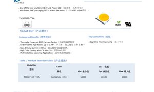
This document details the specifications for a 3030 form-factor mid-power LED utilizing an Epoxy Molding Compound (EMC) package. The product is designed to offer an optimal balance between luminous efficacy (lm/W) and cost-effectiveness (lm/$) within the mid-power segment. It is engineered for applications requiring reliable performance and high-quality light output.
1.1 Core Advantages and Target Market
The primary advantages of this LED series include its thermally enhanced EMC package design, which improves heat dissipation and long-term reliability. It bridges the gap between mid-power and high-power applications, capable of handling up to 0.8W. With a maximum driving current of 240mA and a minimum Color Rendering Index (CRI) of 70, it is suitable for applications demanding good color quality. The device is compatible with Pb-free reflow soldering processes. A key target application identified is Daytime Running Lamps (DRL).
2. Technical Parameter Analysis
All measurements are specified under standard test conditions of Forward Current (IF) = 150mA, Ambient Temperature (Ta) = 25°C, and Relative Humidity (RH) = 60% unless otherwise stated.
2.1 Photometric and Color Characteristics
The Cool White variant has a correlated color temperature (CCT) range from 5300K to 6488K, with a typical value of 6018K. The minimum CRI (Ra) is 70, with a typical value of 71.5. The luminous flux output has a measurement tolerance of ±7%, while the CRI measurement tolerance is ±2. The CCT is derived from the CIE 1931 Chromaticity diagram. It is important to note that the lumen maintenance table is for reference only.
2.2 Electrical and Thermal Parameters
The forward voltage (VF) typically measures 3.1V, with a range from 2.8V (Min) to 3.4V (Max) at 150mA. The reverse current (IR) is a maximum of 10 µA at a reverse voltage (VR) of 5V. The viewing angle (2θ½), defined as the off-axis angle where luminous intensity is half of the peak intensity, is typically 120°. The thermal resistance from junction to solder point (Rth j-sp) is typically 11 °C/W. The device has an Electrostatic Discharge (ESD) withstand capability of 2000V.
2.3 Absolute Maximum Ratings
Operating the device beyond these limits may cause permanent damage. The absolute maximum ratings are: Continuous Forward Current (IF): 240 mA; Pulse Forward Current (IFP): 300 mA (Pulse Width ≤ 100µs, Duty Cycle ≤ 1/10); Power Dissipation (PD): 816 mW; Reverse Voltage (VR): 5 V; Operating Temperature (Topr): -40°C to +105°C; Storage Temperature (Tstg): -40°C to +105°C; Junction Temperature (Tj): 125 °C; Soldering Temperature (Tsld): 230°C or 260°C for 10 seconds. Care must be taken to ensure power dissipation does not exceed the absolute maximum rating.
3. Performance Curve Analysis
3.1 Spectral and Angular Distribution
The relative spectral power distribution (Fig. 1) defines the color characteristics of the Cool White LED. The viewing angle distribution (Fig. 2) shows the typical 120° beam pattern, confirming the Lambertian or near-Lambertian emission profile common for this package type.
3.2 Forward Current Characteristics
The relationship between forward current and relative luminous flux (Fig. 3) shows that light output increases with current but will eventually saturate and degrade at higher currents due to thermal effects. The forward voltage vs. forward current curve (Fig. 4) demonstrates the diode's characteristic exponential behavior, with VF increasing logarithmically with IF.
3.3 Temperature Dependency
The shift in CIE chromaticity coordinates (x, y) with ambient temperature (Fig. 5) is critical for color-critical applications, showing how the white point may drift. The relative luminous flux decreases as ambient temperature increases (Fig. 6), a key consideration for thermal management design. Similarly, forward voltage typically decreases with increasing temperature (Fig. 7).
3.4 Derating and Maximum Current
Figure 8 illustrates the maximum allowable forward current as a function of ambient temperature for two different junction-to-ambient thermal resistance (Rth j-a) values: 30°C/W and 35°C/W. This graph is essential for determining the safe operating current in a given thermal environment. For example, at an ambient temperature of 85°C with Rth j-a=35°C/W, the maximum current is significantly derated from the absolute maximum of 240mA.
4. Color Bin Structure
The LEDs are sorted into bins based on their chromaticity coordinates to ensure color consistency within an application. Figure 9 shows the CIE 1931 chromaticity diagram with the defined bin structure. Table 5 provides a detailed description of the bin codes. The measurement uncertainty for the color coordinates is ± 0.007. All binning is performed under standard conditions (IF=150mA, Ta=25°C).
5. Application Guidelines and Design Considerations
5.1 Typical Application Scenarios
This LED is well-suited for a variety of general lighting applications due to its balance of efficiency, cost, and quality. The datasheet specifically mentions Daytime Running Lamps (DRL). Other potential applications include indoor lighting (bulbs, tubes, panels), architectural lighting, signage, and backlighting for displays where a cool white color temperature is desired.
5.2 Thermal Management
Effective thermal management is paramount for achieving rated performance and longevity. The typical thermal resistance of 11 °C/W from junction to solder point means the PCB design must provide a low thermal impedance path to the ambient. Using appropriate thermal vias, copper area, and possibly a metal-core PCB (MCPCB) is recommended for high-current or high-ambient-temperature operation. Always refer to the derating curve (Fig. 8) to select the appropriate drive current.
5.3 Electrical Drive Considerations
A constant current driver is strongly recommended over a constant voltage source to ensure stable light output and prevent thermal runaway. The driver should be selected to operate within the specified current range (up to 240mA continuous). The forward voltage variation (2.8V to 3.4V) must be accounted for in the driver's compliance voltage. For pulse operation (IFP), strict adherence to the pulse width (≤100µs) and duty cycle (≤1/10) limits is required.
5.4 Soldering and Handling
The device is compatible with lead-free reflow soldering profiles. The maximum soldering temperature is 230°C or 260°C for 10 seconds. Standard IPC/JEDEC J-STD-020 guidelines for moisture sensitivity and reflow profiles should be followed. Standard ESD precautions must be observed during handling and assembly, as the device is rated for 2000V HBM.
6. Comparison and Differentiation
Compared to traditional mid-power LEDs in plastic packages, the EMC package offers superior thermal performance and resistance to yellowing from UV exposure, leading to better lumen maintenance and longer lifetime. The 3030 footprint provides a larger thermal pad than smaller packages (e.g., 2835), allowing for higher power dissipation (up to 0.8W) while maintaining a moderate form factor. The specified CRI of 70+ offers better color quality than many standard mid-power LEDs, making it suitable for applications where color rendition is a consideration.
7. Frequently Asked Questions (FAQ)
Q: What is the main advantage of the EMC package?
A: The EMC package provides enhanced thermal conductivity compared to standard PPA plastic, leading to lower junction temperature, higher maximum drive current capability, and improved long-term reliability and lumen maintenance.
Q: How do I interpret the derating curve (Fig. 8)?
A: The curve shows the maximum continuous current you can safely apply at a given ambient temperature for a specific thermal resistance (Rth j-a) of your system. You must know your system's effective Rth j-a to use the correct curve. Exceeding these limits risks overheating and premature failure.
Q: Can I drive this LED at 240mA continuously?
A: You can only drive it at 240mA if the junction temperature is kept at or below 125°C. In most practical applications, especially at higher ambient temperatures, the current will need to be derated according to Fig. 8 to stay within the Tj limit.
Q: What is the purpose of the color binning?
A: Manufacturing variations cause slight differences in chromaticity between individual LEDs. Binning groups LEDs with very similar color coordinates together. Using LEDs from the same or adjacent bins in a fixture ensures uniform white color appearance without visible color differences (color mismatch).
8. Operational Principles and Trends
8.1 Basic Operating Principle
This is a solid-state light source based on a semiconductor diode. When a forward voltage exceeding the diode's threshold is applied, electrons and holes recombine within the active region of the semiconductor chip (typically based on InGaN for blue/white LEDs), releasing energy in the form of photons (light). The cool white light is generated by a combination of a blue LED chip and a phosphor coating. The blue light from the chip excites the yellow (and sometimes red/green) phosphors, and the mixture of blue and yellow light is perceived as white.
8.2 Industry Trends
The mid-power LED segment, particularly in packages like 3030 and 2835, continues to be a dominant force in general lighting due to its excellent cost-to-performance ratio. Trends include ongoing improvements in luminous efficacy (lm/W) through chip and phosphor technology advancements, the push for higher CRI and better color consistency (tighter binning), and the development of packages with even lower thermal resistance to enable higher drive currents and power densities from the same footprint. The move towards EMC and other high-performance package materials from standard plastics is a clear trend for enhanced reliability in demanding applications.
LED Specification Terminology
Complete explanation of LED technical terms
Photoelectric Performance
| Term | Unit/Representation | Simple Explanation | Why Important |
|---|---|---|---|
| Luminous Efficacy | lm/W (lumens per watt) | Light output per watt of electricity, higher means more energy efficient. | Directly determines energy efficiency grade and electricity cost. |
| Luminous Flux | lm (lumens) | Total light emitted by source, commonly called "brightness". | Determines if the light is bright enough. |
| Viewing Angle | ° (degrees), e.g., 120° | Angle where light intensity drops to half, determines beam width. | Affects illumination range and uniformity. |
| CCT (Color Temperature) | K (Kelvin), e.g., 2700K/6500K | Warmth/coolness of light, lower values yellowish/warm, higher whitish/cool. | Determines lighting atmosphere and suitable scenarios. |
| CRI / Ra | Unitless, 0–100 | Ability to render object colors accurately, Ra≥80 is good. | Affects color authenticity, used in high-demand places like malls, museums. |
| SDCM | MacAdam ellipse steps, e.g., "5-step" | Color consistency metric, smaller steps mean more consistent color. | Ensures uniform color across same batch of LEDs. |
| Dominant Wavelength | nm (nanometers), e.g., 620nm (red) | Wavelength corresponding to color of colored LEDs. | Determines hue of red, yellow, green monochrome LEDs. |
| Spectral Distribution | Wavelength vs intensity curve | Shows intensity distribution across wavelengths. | Affects color rendering and quality. |
Electrical Parameters
| Term | Symbol | Simple Explanation | Design Considerations |
|---|---|---|---|
| Forward Voltage | Vf | Minimum voltage to turn on LED, like "starting threshold". | Driver voltage must be ≥Vf, voltages add up for series LEDs. |
| Forward Current | If | Current value for normal LED operation. | Usually constant current drive, current determines brightness & lifespan. |
| Max Pulse Current | Ifp | Peak current tolerable for short periods, used for dimming or flashing. | Pulse width & duty cycle must be strictly controlled to avoid damage. |
| Reverse Voltage | Vr | Max reverse voltage LED can withstand, beyond may cause breakdown. | Circuit must prevent reverse connection or voltage spikes. |
| Thermal Resistance | Rth (°C/W) | Resistance to heat transfer from chip to solder, lower is better. | High thermal resistance requires stronger heat dissipation. |
| ESD Immunity | V (HBM), e.g., 1000V | Ability to withstand electrostatic discharge, higher means less vulnerable. | Anti-static measures needed in production, especially for sensitive LEDs. |
Thermal Management & Reliability
| Term | Key Metric | Simple Explanation | Impact |
|---|---|---|---|
| Junction Temperature | Tj (°C) | Actual operating temperature inside LED chip. | Every 10°C reduction may double lifespan; too high causes light decay, color shift. |
| Lumen Depreciation | L70 / L80 (hours) | Time for brightness to drop to 70% or 80% of initial. | Directly defines LED "service life". |
| Lumen Maintenance | % (e.g., 70%) | Percentage of brightness retained after time. | Indicates brightness retention over long-term use. |
| Color Shift | Δu′v′ or MacAdam ellipse | Degree of color change during use. | Affects color consistency in lighting scenes. |
| Thermal Aging | Material degradation | Deterioration due to long-term high temperature. | May cause brightness drop, color change, or open-circuit failure. |
Packaging & Materials
| Term | Common Types | Simple Explanation | Features & Applications |
|---|---|---|---|
| Package Type | EMC, PPA, Ceramic | Housing material protecting chip, providing optical/thermal interface. | EMC: good heat resistance, low cost; Ceramic: better heat dissipation, longer life. |
| Chip Structure | Front, Flip Chip | Chip electrode arrangement. | Flip chip: better heat dissipation, higher efficacy, for high-power. |
| Phosphor Coating | YAG, Silicate, Nitride | Covers blue chip, converts some to yellow/red, mixes to white. | Different phosphors affect efficacy, CCT, and CRI. |
| Lens/Optics | Flat, Microlens, TIR | Optical structure on surface controlling light distribution. | Determines viewing angle and light distribution curve. |
Quality Control & Binning
| Term | Binning Content | Simple Explanation | Purpose |
|---|---|---|---|
| Luminous Flux Bin | Code e.g., 2G, 2H | Grouped by brightness, each group has min/max lumen values. | Ensures uniform brightness in same batch. |
| Voltage Bin | Code e.g., 6W, 6X | Grouped by forward voltage range. | Facilitates driver matching, improves system efficiency. |
| Color Bin | 5-step MacAdam ellipse | Grouped by color coordinates, ensuring tight range. | Guarantees color consistency, avoids uneven color within fixture. |
| CCT Bin | 2700K, 3000K etc. | Grouped by CCT, each has corresponding coordinate range. | Meets different scene CCT requirements. |
Testing & Certification
| Term | Standard/Test | Simple Explanation | Significance |
|---|---|---|---|
| LM-80 | Lumen maintenance test | Long-term lighting at constant temperature, recording brightness decay. | Used to estimate LED life (with TM-21). |
| TM-21 | Life estimation standard | Estimates life under actual conditions based on LM-80 data. | Provides scientific life prediction. |
| IESNA | Illuminating Engineering Society | Covers optical, electrical, thermal test methods. | Industry-recognized test basis. |
| RoHS / REACH | Environmental certification | Ensures no harmful substances (lead, mercury). | Market access requirement internationally. |
| ENERGY STAR / DLC | Energy efficiency certification | Energy efficiency and performance certification for lighting. | Used in government procurement, subsidy programs, enhances competitiveness. |