1. Product Overview
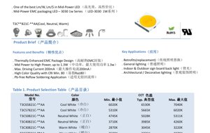
This document details the specifications for the 3030 series mid-power LED components. Designed for general lighting applications, this series utilizes a Thermally Enhanced Epoxy Molding Compound (EMC) package, offering an optimal balance of luminous efficacy, cost-effectiveness, and reliability. The series is characterized by its 3.0mm x 3.0mm footprint and is capable of operating at power levels up to 1.3W, positioning it between traditional mid-power and entry-level high-power LEDs.
1.1 Core Advantages and Positioning
The primary value proposition of this LED series lies in achieving one of the best ratios of lumens per watt (lm/W) and lumens per dollar (lm/$) within the mid-power LED category. The EMC package provides superior thermal management compared to standard PPA or PCT plastics, allowing for higher drive currents and improved long-term lumen maintenance. The product is suitable for lead-free reflow soldering processes, aligning with modern, environmentally conscious manufacturing standards.
1.2 Target Applications
This versatile LED series is engineered for a broad spectrum of lighting solutions. Key application areas include retrofit lamps designed to replace traditional incandescent or fluorescent sources, general ambient lighting for residential and commercial spaces, backlighting for indoor and outdoor signage, and architectural or decorative lighting where both performance and aesthetic color quality are important.
2. In-Depth Technical Parameter Analysis
All parameters are measured under standard test conditions of Ta = 25°C and 60% relative humidity unless otherwise specified.
2.1 Electro-Optical Characteristics
The photometric performance is defined at a forward current (IF) of 150mA. The series offers a range of Correlated Color Temperatures (CCT) from warm white (2725K) to cool white (6530K), all with a minimum Color Rendering Index (CRI or Ra) of 80. Typical luminous flux values vary by CCT bin, ranging from approximately 107 lm to 120 lm at 150mA. It is important to note the stated measurement tolerances: ±7% for luminous flux and ±2 for CRI. The dominant viewing angle (2Θ1/2) is 110 degrees, providing a wide beam distribution suitable for general illumination.
2.2 Electrical and Thermal Parameters
The typical forward voltage (VF) is 6.8V at 150mA, with a tolerance of ±0.1V. The absolute maximum forward current is 200mA DC, with a pulsed forward current (IFP) of 300mA allowed under specific conditions (pulse width ≤ 100µs, duty cycle ≤ 1/10). The maximum power dissipation is 1360 mW. A critical thermal parameter is the junction-to-solder point thermal resistance (Rth j-sp), which is typically 17 °C/W. This low thermal resistance is a direct benefit of the EMC package, enabling efficient heat transfer away from the LED junction.
2.3 Absolute Maximum Ratings
Operating the device beyond these limits may cause permanent damage. Key ratings include: Forward Current: 200 mA; Reverse Voltage: 5 V; Junction Temperature: 115 °C; Operating Temperature Range: -40 to +85 °C; Storage Temperature Range: -40 to +85 °C. The soldering temperature profile must not exceed 230°C or 260°C for more than 10 seconds.
3. Binning System Explanation
To ensure color and brightness consistency in production, LEDs are sorted into bins.
3.1 Color (CCT) Binning
The product uses an elliptical binning structure on the CIE 1931 chromaticity diagram, compliant with Energy Star requirements for the 2600K to 7000K range. Six primary color codes are defined (e.g., 27M5, 30M5...65M6), each with a center coordinate (x, y), semi-major axis (a), semi-minor axis (b), and angle (Φ). The measurement uncertainty for color coordinates is ±0.007. This tight binning ensures minimal visible color difference within a single lighting fixture.
3.2 Luminous Flux Binning
Within each color bin, LEDs are further sorted by their luminous flux output at 150mA. Multiple flux ranks are defined (e.g., 2A, 2B, 2C, 2D, 2E), each covering a specific lumen range (e.g., 94-100 lm, 100-107 lm, etc.). This allows designers to select bins that match the precise brightness requirements of their application.
3.3 Forward Voltage Binning
LEDs are also binned according to their forward voltage drop at the test current. While the specific code values and ranges are detailed in the datasheet table, this binning helps in designing more efficient and consistent driver circuits, especially in multi-LED strings.
4. Performance Curve Analysis
4.1 IV Characteristics and Relative Luminous Flux
Figure 3 shows the relationship between forward current and relative luminous flux. The output is relatively linear up to the maximum rated current, but designers should note that efficacy (lm/W) typically decreases at higher currents due to increased thermal load and efficiency droop. Figure 4 illustrates the forward voltage versus current curve, which is essential for driver design to ensure proper voltage compliance.
4.2 Temperature Dependence
Figures 6 and 7 demonstrate the effects of ambient temperature (Ta) on performance. Luminous output decreases as temperature increases, a characteristic of all LEDs. Conversely, forward voltage decreases with rising temperature. Figure 5 shows the shift in chromaticity coordinates (CIE x, y) with temperature, which is crucial for applications requiring stable color points. Figure 8 provides a critical design graph: the maximum allowable forward current versus ambient temperature for two different thermal resistance scenarios (Rj-a=35°C/W and 45°C/W). This graph is vital for determining safe operating currents in real-world thermal environments.
4.3 Spectral and Angular Distribution
Figure 1 presents a typical spectral power distribution, showing a broad phosphor-converted white light spectrum characteristic of a blue pump LED with a phosphor coating. Figure 2 depicts the spatial intensity distribution (viewing angle pattern), confirming the Lambertian-like wide beam pattern indicated by the 110-degree viewing angle.
5. Application Guidelines and Design Considerations
5.1 Thermal Management
Effective heat sinking is paramount for performance and longevity. Despite the low Rth j-sp, the thermal path from the solder point to the ambient environment (Rth sp-a) must be minimized through proper PCB design (using thermal vias, sufficient copper area) and system-level heatsinking. Refer to Figure 8 to derate the operating current based on the estimated Ta and system Rj-a.
5.2 Electrical Drive
A constant current driver is strongly recommended to ensure stable light output and color. The driver should be designed to operate within the Absolute Maximum Ratings, accounting for voltage binning and temperature effects on VF. For designs near the maximum current, consider the trade-off between higher light output and reduced efficacy/lifetime.
5.3 Optical Integration
The 110-degree viewing angle makes these LEDs suitable for applications requiring wide, diffuse illumination without secondary optics. For directional lighting, appropriate lenses or reflectors must be selected. The consistent color and flux binning enable uniform appearance in multi-LED arrays.
6. Soldering and Handling
The component is compatible with standard lead-free reflow soldering profiles. The peak soldering temperature must not exceed 230°C or 260°C, with exposure time above 217°C limited to 60 seconds and time at peak temperature limited to 10 seconds. Standard ESD (Electrostatic Discharge) precautions should be observed during handling, as the device has an ESD withstand voltage of 1000V (Human Body Model).
7. Technical Comparison and Differentiation
The key differentiator of this series is the use of an EMC package in the 3030 mid-power form factor. Compared to standard plastic packages (PPA/PCT), EMC offers significantly higher thermal conductivity and resistance to high temperature and UV exposure, leading to better lumen maintenance and color stability over the product's lifetime. This allows the LED to be driven at higher currents (up to 200mA) than typical mid-power LEDs, bridging the gap to higher-power devices while maintaining the cost and optical advantages of the mid-power platform.
8. Frequently Asked Questions (Based on Technical Parameters)
Q: What is the actual power consumption at the typical operating point?
A: At IF = 150mA and VF = 6.8V, the typical electrical power is 150mA * 6.8V = 1.02W.
Q: How do I select the right CCT and flux bin for my project?
A: Choose the CCT (e.g., 3000K warm white, 4000K neutral white, 6500K cool white) based on the desired ambiance. Select a flux bin based on the target lumen output per LED, considering the binning tables and measurement tolerances. For uniform arrays, specify a single tight bin for both color and flux.
Q: Can I drive this LED at 200mA continuously?
A: You can, but only if the junction temperature is kept well below its maximum of 115°C. This requires excellent thermal management. Refer to Figure 8; at an ambient temperature of 85°C, the maximum allowed current for a system with Rj-a=45°C/W is only about 89mA. Therefore, driving at 200mA is only feasible in very well-cooled, low-ambient-temperature environments.
9. Design and Usage Case Example
Scenario: Designing a 1200 lm LED Bulb Replacement (A19).
Target: 1200 lm, 2700K CCT, 120V AC input.
Design Steps:
1. LED Selection: Choose the T3C27821C-**AA model (2725K CCT). Select a high luminous flux bin (e.g., 2D or 2E) for maximum output per LED.
2. Quantity Calculation: Assuming 115 lm/LED (typical from bin 2D), approximately 1200 lm / 115 lm/LED ≈ 11 LEDs are needed.
3. Electrical Design: Configure the 11 LEDs in a series string. The total forward voltage at 150mA would be ~11 * 6.8V = 74.8V. Select an isolated, constant-current LED driver with an output compliant with 74.8V, 150mA.
4. Thermal Design: The total power dissipation is ~1.02W/LED * 11 LEDs = 11.22W. A significant portion is heat. The bulb must incorporate an aluminum heatsink or similar to maintain the LED solder point temperature below the derating curve in Figure 8, ensuring long life and stable light output.
5. Optical Design: The wide 110-degree beam angle may be sufficient for omnidirectional bulb applications. A diffuser cover would be used to blend the multiple point sources into a uniform glow.
10. Technical Principles and Trends
10.1 Operating Principle
This is a phosphor-converted white LED. The core semiconductor element is a blue light-emitting InGaN (Indium Gallium Nitride) diode. Part of the blue light is absorbed by a cerium-doped yttrium aluminum garnet (YAG:Ce) phosphor coating, which re-emits it as broad-spectrum yellow light. The combination of the remaining blue light and the converted yellow light results in the perception of white light. The ratio of blue to yellow light, controlled by the phosphor composition and thickness, determines the Correlated Color Temperature (CCT).
10.2 Industry Trends
The mid-power LED segment continues to evolve towards higher efficacy (lm/W) and improved reliability at competitive cost points. The adoption of EMC and other high-performance package materials (like ceramic and thermoplastics) is a key trend to enable higher drive currents and better lumen maintenance. There is also a continuous push for higher Color Rendering Index (CRI) values and more precise color consistency (tighter binning) to meet the demands of quality-conscious lighting markets. Furthermore, the integration of these LEDs onto standardized boards like COBs (Chip-on-Board) or flexible strips is a common application trend for simplified assembly and improved thermal performance.
LED Specification Terminology
Complete explanation of LED technical terms
Photoelectric Performance
| Term | Unit/Representation | Simple Explanation | Why Important |
|---|---|---|---|
| Luminous Efficacy | lm/W (lumens per watt) | Light output per watt of electricity, higher means more energy efficient. | Directly determines energy efficiency grade and electricity cost. |
| Luminous Flux | lm (lumens) | Total light emitted by source, commonly called "brightness". | Determines if the light is bright enough. |
| Viewing Angle | ° (degrees), e.g., 120° | Angle where light intensity drops to half, determines beam width. | Affects illumination range and uniformity. |
| CCT (Color Temperature) | K (Kelvin), e.g., 2700K/6500K | Warmth/coolness of light, lower values yellowish/warm, higher whitish/cool. | Determines lighting atmosphere and suitable scenarios. |
| CRI / Ra | Unitless, 0–100 | Ability to render object colors accurately, Ra≥80 is good. | Affects color authenticity, used in high-demand places like malls, museums. |
| SDCM | MacAdam ellipse steps, e.g., "5-step" | Color consistency metric, smaller steps mean more consistent color. | Ensures uniform color across same batch of LEDs. |
| Dominant Wavelength | nm (nanometers), e.g., 620nm (red) | Wavelength corresponding to color of colored LEDs. | Determines hue of red, yellow, green monochrome LEDs. |
| Spectral Distribution | Wavelength vs intensity curve | Shows intensity distribution across wavelengths. | Affects color rendering and quality. |
Electrical Parameters
| Term | Symbol | Simple Explanation | Design Considerations |
|---|---|---|---|
| Forward Voltage | Vf | Minimum voltage to turn on LED, like "starting threshold". | Driver voltage must be ≥Vf, voltages add up for series LEDs. |
| Forward Current | If | Current value for normal LED operation. | Usually constant current drive, current determines brightness & lifespan. |
| Max Pulse Current | Ifp | Peak current tolerable for short periods, used for dimming or flashing. | Pulse width & duty cycle must be strictly controlled to avoid damage. |
| Reverse Voltage | Vr | Max reverse voltage LED can withstand, beyond may cause breakdown. | Circuit must prevent reverse connection or voltage spikes. |
| Thermal Resistance | Rth (°C/W) | Resistance to heat transfer from chip to solder, lower is better. | High thermal resistance requires stronger heat dissipation. |
| ESD Immunity | V (HBM), e.g., 1000V | Ability to withstand electrostatic discharge, higher means less vulnerable. | Anti-static measures needed in production, especially for sensitive LEDs. |
Thermal Management & Reliability
| Term | Key Metric | Simple Explanation | Impact |
|---|---|---|---|
| Junction Temperature | Tj (°C) | Actual operating temperature inside LED chip. | Every 10°C reduction may double lifespan; too high causes light decay, color shift. |
| Lumen Depreciation | L70 / L80 (hours) | Time for brightness to drop to 70% or 80% of initial. | Directly defines LED "service life". |
| Lumen Maintenance | % (e.g., 70%) | Percentage of brightness retained after time. | Indicates brightness retention over long-term use. |
| Color Shift | Δu′v′ or MacAdam ellipse | Degree of color change during use. | Affects color consistency in lighting scenes. |
| Thermal Aging | Material degradation | Deterioration due to long-term high temperature. | May cause brightness drop, color change, or open-circuit failure. |
Packaging & Materials
| Term | Common Types | Simple Explanation | Features & Applications |
|---|---|---|---|
| Package Type | EMC, PPA, Ceramic | Housing material protecting chip, providing optical/thermal interface. | EMC: good heat resistance, low cost; Ceramic: better heat dissipation, longer life. |
| Chip Structure | Front, Flip Chip | Chip electrode arrangement. | Flip chip: better heat dissipation, higher efficacy, for high-power. |
| Phosphor Coating | YAG, Silicate, Nitride | Covers blue chip, converts some to yellow/red, mixes to white. | Different phosphors affect efficacy, CCT, and CRI. |
| Lens/Optics | Flat, Microlens, TIR | Optical structure on surface controlling light distribution. | Determines viewing angle and light distribution curve. |
Quality Control & Binning
| Term | Binning Content | Simple Explanation | Purpose |
|---|---|---|---|
| Luminous Flux Bin | Code e.g., 2G, 2H | Grouped by brightness, each group has min/max lumen values. | Ensures uniform brightness in same batch. |
| Voltage Bin | Code e.g., 6W, 6X | Grouped by forward voltage range. | Facilitates driver matching, improves system efficiency. |
| Color Bin | 5-step MacAdam ellipse | Grouped by color coordinates, ensuring tight range. | Guarantees color consistency, avoids uneven color within fixture. |
| CCT Bin | 2700K, 3000K etc. | Grouped by CCT, each has corresponding coordinate range. | Meets different scene CCT requirements. |
Testing & Certification
| Term | Standard/Test | Simple Explanation | Significance |
|---|---|---|---|
| LM-80 | Lumen maintenance test | Long-term lighting at constant temperature, recording brightness decay. | Used to estimate LED life (with TM-21). |
| TM-21 | Life estimation standard | Estimates life under actual conditions based on LM-80 data. | Provides scientific life prediction. |
| IESNA | Illuminating Engineering Society | Covers optical, electrical, thermal test methods. | Industry-recognized test basis. |
| RoHS / REACH | Environmental certification | Ensures no harmful substances (lead, mercury). | Market access requirement internationally. |
| ENERGY STAR / DLC | Energy efficiency certification | Energy efficiency and performance certification for lighting. | Used in government procurement, subsidy programs, enhances competitiveness. |