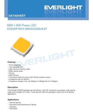
1. Product Overview
The XI3030P is a surface-mount device (SMD) mid-power LED in a PLCC-2 (Plastic Leaded Chip Carrier) package. It is designed as a top-view white LED, offering a combination of high luminous efficacy, excellent color rendering, and a compact form factor. Its primary design goals are energy efficiency and reliable performance for a broad range of lighting applications.
1.1 Core Advantages
The key advantages of this LED package include:
- High Luminous Efficacy: Typical efficacy of 225 lm/W at 65mA and 5000K CCT, contributing to lower energy consumption.
- High Color Rendering Index (CRI): Available with a minimum CRI of 80 (Ra), with options up to 90, ensuring accurate and pleasing color reproduction.
- Wide Viewing Angle: A typical viewing angle (2θ1/2) of 120 degrees provides uniform and broad illumination.
- Compact Form Factor: The small 3.0mm x 3.0mm footprint allows for flexible and dense PCB layout designs.
- Environmental Compliance: The product is Pb-free, compliant with RoHS, EU REACH, and halogen-free standards (Br<900ppm, Cl<900ppm, Br+Cl<1500ppm).
1.2 Target Market & Applications
This LED is an ideal solution for various lighting applications that require a balance of performance, efficiency, and cost. Primary application areas include:
- General Lighting: Suitable for residential, commercial, and industrial ambient lighting fixtures.
- Decorative and Entertainment Lighting: Used in accent lighting, architectural lighting, and stage lighting due to its good color quality.
- Indicators & Illumination: Applicable for backlighting, signage, and status indicators.
- Switch Lights: Can be integrated into illuminated switches and control panels.
2. In-Depth Technical Parameter Analysis
This section provides a detailed, objective interpretation of the key technical parameters specified in the datasheet.
2.1 Electro-Optical Characteristics
The primary performance metrics are defined under standard test conditions (soldering point temperature = 25°C, forward current IF = 65mA).
- Luminous Flux (Φ): The minimum luminous flux varies by product variant, ranging from 37 lm to 39 lm depending on the correlated color temperature (CCT). A tolerance of ±11% applies.
- Forward Voltage (VF): The maximum forward voltage is specified as 2.9V, with a typical tolerance of ±0.1V. Lower VF contributes to higher system efficiency.
- Color Rendering Index (CRI/Ra): The minimum Ra is 80 for the standard series, with a tight tolerance of ±2, ensuring consistent color quality across production batches.
- Viewing Angle (2θ1/2): The typical value is 120 degrees, which is considered a wide viewing angle, suitable for applications requiring diffuse light distribution.
- Efficacy: The typical luminous efficacy is 225 lm/W, measured at 65mA and 5000K CCT. This is a key figure of merit for energy efficiency.
- Reverse Current (IR): Maximum reverse current is 50 µA at a reverse voltage (VR) of 5V, indicating the diode's leakage characteristics.
2.2 Absolute Maximum Ratings
These ratings define the limits beyond which permanent damage to the device may occur. Operation should always be maintained within these limits.
- Forward Current (IF): 180 mA (continuous).
- Peak Forward Current (IFP): 300 mA, permissible only under pulsed conditions (duty cycle 1/10, pulse width 10ms).
- Power Dissipation (Pd): 580 mW.
- Operating & Storage Temperature: -40°C to +85°C (operating), -40°C to +100°C (storage).
- Thermal Resistance (RθJ-S): Junction-to-soldering point thermal resistance is 21 °C/W. This parameter is critical for thermal management design.
- Junction Temperature (Tj): Maximum allowable junction temperature is 115°C.
- Soldering Temperature: Reflow soldering: 260°C max for 10 seconds. Hand soldering: 350°C max for 3 seconds.
Important Note: The device is sensitive to electrostatic discharge (ESD). Proper ESD handling precautions must be observed during assembly and handling.
3. Binning System Explanation
The product uses a comprehensive binning system to ensure electrical and optical consistency. The product number explains the bin codes.
3.1 Product Number Decoding
Example: XI3030P/KKX-5M403929U6/2T
- XI3030P: Package series and size (3.0mm x 3.0mm).
- KKX-5M: Internal series code.
- First 'XX' (40): Represents Correlated Color Temperature (CCT). '40' = 4000K.
- Second 'XX' (39): Represents the minimum luminous flux bin code. '39' = 39 lm (min).
- Third 'XX' (29): Represents the maximum forward voltage bin code. '29' corresponds to VF max of 2.9V.
- U6: Forward current index, indicating the operating current is 65mA.
- 2T: Additional product variant code.
3.2 Color Rendering Index (CRI) Binning
The datasheet provides a table mapping single-letter symbols to minimum CRI values:
- M: CRI 60, N: 65, L: 70, Q: 75, K: 80, P: 85, H: 90.
3.3 Luminous Flux Binning
Luminous flux is binned according to CCT. For example:
- 3000K: Bin codes 37L2 (37-39 lm), 39L2 (39-41 lm), 41L2 (41-43 lm).
- 4000K/5000K/5700K: Bin codes 39L2 (39-41 lm), 41L2 (41-43 lm), 43L2 (43-45 lm).
- 6500K: Bin codes 38L2 (38-40 lm), 40L2 (40-42 lm), 42L2 (42-44 lm).
3.4 Forward Voltage Binning
Forward voltage is grouped under code '2629' with three sub-bins:
- 26A: 2.6V - 2.7V
- 27A: 2.7V - 2.8V
- 28A: 2.8V - 2.9V (Max)
3.5 Chromaticity Binning (MacAdam Ellipses)
The LED's color point (chromaticity coordinates) is controlled to within defined ellipses on the CIE 1931 diagram to ensure color consistency.
- MacAdam 3-step: Tighter color control, meaning LEDs within a 3-step ellipse are virtually indistinguishable in color to the human eye under standard conditions.
- MacAdam 5-step: Standard color control, suitable for most general lighting applications where slight color variation is acceptable.
4. Performance Curve Analysis
The typical curves provide insight into the LED's behavior under varying operating conditions.
4.1 Forward Voltage vs. Junction Temperature (Fig.1)
The forward voltage (VF) has a negative temperature coefficient. As the junction temperature (Tj) increases from 25°C to 115°C, VF decreases linearly by approximately 0.2V. This characteristic is important for constant-current driver design and thermal compensation considerations.
4.2 Relative Luminous Intensity vs. Forward Current (Fig.2)
Luminous output is sub-linear with current. While output increases with current, the efficacy (lumens per watt) typically decreases at higher currents due to increased thermal and efficiency droop. Operating at the recommended 65mA ensures optimal efficacy and longevity.
4.3 Relative Luminous Flux vs. Junction Temperature (Fig.3)
Luminous output decreases as junction temperature rises. The curve shows that at a Tj of 100°C, the relative luminous flux is approximately 85% of its value at 25°C. Effective thermal management (low RθJ-A) is crucial to maintain light output and lifespan.
4.4 Forward Current vs. Forward Voltage (IV Curve) (Fig.4)
This graph shows the typical exponential relationship between current and voltage for a diode. It is essential for selecting the appropriate driving method (constant current is mandatory for LEDs).
4.5 Maximum Driving Current vs. Soldering Temperature (Fig.5)
This derating curve indicates that the maximum permissible forward current decreases as the temperature at the soldering point increases. This is a critical design rule for ensuring the LED operates within its safe operating area (SOA) under all environmental conditions.
4.6 Radiation Pattern (Fig.6)
The polar diagram confirms the wide, Lambertian-like emission pattern with a typical 120° viewing angle. The intensity is fairly uniform across a broad central region.
4.7 Spectrum Distribution
The spectral power distribution graph (not detailed in text but referenced) would show a broad blue pump LED peak and a broader phosphor-converted yellow emission peak, characteristic of white phosphor-converted LEDs. The exact shape determines the CCT and CRI.
5. Soldering and Assembly Guidelines
5.1 Reflow Soldering Parameters
The LED is compatible with standard infrared or convection reflow processes. The critical parameter is the peak soldering temperature, which must not exceed 260°C for more than 10 seconds. A standard lead-free reflow profile (e.g., JEDEC J-STD-020) is recommended. Precise control is necessary to avoid thermal damage to the plastic package and the internal die attach.
5.2 Hand Soldering
If hand soldering is necessary, the iron tip temperature should be controlled to a maximum of 350°C, and the contact time with each solder pad must be limited to 3 seconds or less to prevent overheating.
5.3 Storage Conditions
LEDs should be stored in their original moisture-barrier bags (if classified as moisture-sensitive) in an environment with temperature between -40°C and +100°C and low humidity. Follow standard IPC/JEDEC guidelines for handling moisture-sensitive devices (MSD) if applicable.
6. Application Design Considerations
6.1 Driver Selection
A constant current driver is essential. The recommended operating current is 65mA. The driver should be selected based on the required string voltage (sum of LED VF) and must include appropriate protection features like over-current, over-voltage, and open/short circuit protection. The negative VF temperature coefficient should be considered in the driver's feedback loop design for some precision applications.
6.2 Thermal Management
With a junction-to-solder point thermal resistance (RθJ-S) of 21°C/W, effective heat sinking is necessary, especially when operating at or near maximum ratings. The PCB should have adequate thermal vias and copper area connected to the LED's thermal pad (if present in the footprint) to dissipate heat. The maximum junction temperature of 115°C should not be exceeded. Use the formula: Tj = Ts + (RθJ-S * Pd), where Ts is the solder point temperature and Pd is the power dissipation (VF * IF).
6.3 Optical Design
The wide 120° viewing angle makes this LED suitable for applications requiring diffuse, even illumination without secondary optics. For focused beams, appropriate primary optics (lenses or reflectors) must be designed considering the LED's emission pattern and physical size.
7. Technical Comparison & Differentiation
While a direct side-by-side comparison with other products is not provided in the datasheet, the XI3030P's key differentiating features based on its specifications are:
- Balance of Efficacy and CRI: A typical efficacy of 225 lm/W at CRI 80 offers a good balance, whereas some competitors may offer higher efficacy at lower CRI or vice versa.
- Comprehensive Binning: The detailed binning for flux, voltage, and chromaticity (3-step/5-step MacAdam ellipses) allows for tighter system design and better color consistency in multi-LED fixtures compared to products with looser binning.
- Robust Maximum Ratings: A relatively high maximum junction temperature (115°C) and power dissipation (580mW) provide a wider safety margin and design flexibility in thermally challenging environments.
- Environmental Compliance: Full compliance with modern environmental standards (RoHS, REACH, Halogen-Free) is a baseline requirement but is clearly stated as a feature.
8. Frequently Asked Questions (Based on Technical Parameters)
Q1: Can I drive this LED at 150mA for higher output?
A: No. The absolute maximum continuous forward current is 180mA, but the recommended operating condition is 65mA. Operating at 150mA would significantly increase junction temperature, reduce efficacy, accelerate lumen depreciation, and likely void the warranty. Always design for the recommended current.
Q2: What is the difference between the 3-step and 5-step MacAdam ellipse bins?
A: A 3-step ellipse represents a tighter color control where LEDs are nearly indistinguishable in color to most observers. A 5-step ellipse allows for slightly more color variation, which may be noticeable in side-by-side comparison but is acceptable for many applications. Choice depends on the color uniformity requirements of the final product.
Q3: How do I calculate the required heatsink?
A: You need to determine the target solder point temperature (Ts). Using the formula Tj = Ts + (RθJ-S * Pd), set Tj to a safe value below 115°C (e.g., 105°C). Calculate Pd as VF * IF (e.g., 2.9V * 0.065A = 0.1885W). Then, Ts_max = Tj_max - (21°C/W * 0.1885W) ≈ 105°C - 4°C ≈ 101°C. The thermal design of the PCB and system must ensure the solder point stays below this calculated Ts_max.
Q4: Is a constant voltage supply suitable?
A: No. LEDs are current-driven devices. A small change in forward voltage (due to temperature or bin variation) causes a large change in current with a constant voltage source, potentially leading to thermal runaway and failure. Always use a constant current driver or a current-limiting circuit.
9. Design and Usage Case Study
Scenario: Designing a linear LED fixture for office ambient lighting.
- Requirements: Neutral white light (4000K), good color rendering (CRI >80), high efficiency, and uniform illumination over a 2-meter length.
- Part Selection: XI3030P/KKX-5M403929U6/2T is chosen for its 4000K CCT, CRI 80, and high efficacy.
- Thermal Design: The fixture uses an aluminum PCB (MCPCB) with a thermal conductivity of 1-2 W/mK. The calculated power per LED is ~0.19W. With 100 LEDs spaced evenly on a 2m aluminum channel acting as a heatsink, the thermal simulation confirms the junction temperature remains below 90°C in a 25°C ambient environment.
- Electrical Design: LEDs are arranged in series strings of 20 (total VF ~58V max). A constant current driver with an output of 65mA and a voltage range covering 58V is selected. Over-voltage protection is included.
- Optical Design: The wide 120° beam angle of the LED, combined with a milky-white polycarbonate diffuser placed at a calculated distance, achieves the desired uniform illumination without visible hotspots, meeting the office lighting standards.
10. Technology Principle Introduction
The XI3030P is a phosphor-converted white LED. The fundamental principle involves a semiconductor chip, typically made of indium gallium nitride (InGaN), which emits blue light when forward biased (electroluminescence). This blue light is partially absorbed by a phosphor layer (e.g., YAG:Ce) deposited on or around the chip. The phosphor down-converts a portion of the blue photons into photons across a broad spectrum in the yellow and red regions. The mixture of the remaining blue light and the phosphor-emitted yellow/red light is perceived by the human eye as white light. The exact ratio of blue to yellow and the phosphor composition determine the correlated color temperature (CCT) and color rendering index (CRI) of the emitted white light.
11. Industry Trends
The mid-power LED segment, represented by packages like the XI3030P, continues to evolve. Objective industry trends include:
- Increased Efficacy: Ongoing improvements in internal quantum efficiency (IQE) of blue chips, phosphor conversion efficiency, and light extraction from the package drive efficacy higher.
- Enhanced Color Quality: Demand for higher CRI (90+) and improved color consistency (tighter MacAdam ellipses) is growing, especially in commercial and retail lighting.
- Improved Reliability & Lifetime: Advancements in packaging materials (mold compounds, substrates) and manufacturing processes aim to reduce lumen depreciation and increase operational lifetime (L90).
- Miniaturization & Integration: While 3030 is a standard size, there is a trend towards smaller packages with comparable or better performance, as well as integrated modules combining multiple LEDs and drivers.
- Smart & Tunable Lighting: There is increasing integration of LEDs with control electronics to enable features like dimming, color temperature tuning (CCT tunable), and connectivity for IoT-based lighting systems.
LED Specification Terminology
Complete explanation of LED technical terms
Photoelectric Performance
| Term | Unit/Representation | Simple Explanation | Why Important |
|---|---|---|---|
| Luminous Efficacy | lm/W (lumens per watt) | Light output per watt of electricity, higher means more energy efficient. | Directly determines energy efficiency grade and electricity cost. |
| Luminous Flux | lm (lumens) | Total light emitted by source, commonly called "brightness". | Determines if the light is bright enough. |
| Viewing Angle | ° (degrees), e.g., 120° | Angle where light intensity drops to half, determines beam width. | Affects illumination range and uniformity. |
| CCT (Color Temperature) | K (Kelvin), e.g., 2700K/6500K | Warmth/coolness of light, lower values yellowish/warm, higher whitish/cool. | Determines lighting atmosphere and suitable scenarios. |
| CRI / Ra | Unitless, 0–100 | Ability to render object colors accurately, Ra≥80 is good. | Affects color authenticity, used in high-demand places like malls, museums. |
| SDCM | MacAdam ellipse steps, e.g., "5-step" | Color consistency metric, smaller steps mean more consistent color. | Ensures uniform color across same batch of LEDs. |
| Dominant Wavelength | nm (nanometers), e.g., 620nm (red) | Wavelength corresponding to color of colored LEDs. | Determines hue of red, yellow, green monochrome LEDs. |
| Spectral Distribution | Wavelength vs intensity curve | Shows intensity distribution across wavelengths. | Affects color rendering and quality. |
Electrical Parameters
| Term | Symbol | Simple Explanation | Design Considerations |
|---|---|---|---|
| Forward Voltage | Vf | Minimum voltage to turn on LED, like "starting threshold". | Driver voltage must be ≥Vf, voltages add up for series LEDs. |
| Forward Current | If | Current value for normal LED operation. | Usually constant current drive, current determines brightness & lifespan. |
| Max Pulse Current | Ifp | Peak current tolerable for short periods, used for dimming or flashing. | Pulse width & duty cycle must be strictly controlled to avoid damage. |
| Reverse Voltage | Vr | Max reverse voltage LED can withstand, beyond may cause breakdown. | Circuit must prevent reverse connection or voltage spikes. |
| Thermal Resistance | Rth (°C/W) | Resistance to heat transfer from chip to solder, lower is better. | High thermal resistance requires stronger heat dissipation. |
| ESD Immunity | V (HBM), e.g., 1000V | Ability to withstand electrostatic discharge, higher means less vulnerable. | Anti-static measures needed in production, especially for sensitive LEDs. |
Thermal Management & Reliability
| Term | Key Metric | Simple Explanation | Impact |
|---|---|---|---|
| Junction Temperature | Tj (°C) | Actual operating temperature inside LED chip. | Every 10°C reduction may double lifespan; too high causes light decay, color shift. |
| Lumen Depreciation | L70 / L80 (hours) | Time for brightness to drop to 70% or 80% of initial. | Directly defines LED "service life". |
| Lumen Maintenance | % (e.g., 70%) | Percentage of brightness retained after time. | Indicates brightness retention over long-term use. |
| Color Shift | Δu′v′ or MacAdam ellipse | Degree of color change during use. | Affects color consistency in lighting scenes. |
| Thermal Aging | Material degradation | Deterioration due to long-term high temperature. | May cause brightness drop, color change, or open-circuit failure. |
Packaging & Materials
| Term | Common Types | Simple Explanation | Features & Applications |
|---|---|---|---|
| Package Type | EMC, PPA, Ceramic | Housing material protecting chip, providing optical/thermal interface. | EMC: good heat resistance, low cost; Ceramic: better heat dissipation, longer life. |
| Chip Structure | Front, Flip Chip | Chip electrode arrangement. | Flip chip: better heat dissipation, higher efficacy, for high-power. |
| Phosphor Coating | YAG, Silicate, Nitride | Covers blue chip, converts some to yellow/red, mixes to white. | Different phosphors affect efficacy, CCT, and CRI. |
| Lens/Optics | Flat, Microlens, TIR | Optical structure on surface controlling light distribution. | Determines viewing angle and light distribution curve. |
Quality Control & Binning
| Term | Binning Content | Simple Explanation | Purpose |
|---|---|---|---|
| Luminous Flux Bin | Code e.g., 2G, 2H | Grouped by brightness, each group has min/max lumen values. | Ensures uniform brightness in same batch. |
| Voltage Bin | Code e.g., 6W, 6X | Grouped by forward voltage range. | Facilitates driver matching, improves system efficiency. |
| Color Bin | 5-step MacAdam ellipse | Grouped by color coordinates, ensuring tight range. | Guarantees color consistency, avoids uneven color within fixture. |
| CCT Bin | 2700K, 3000K etc. | Grouped by CCT, each has corresponding coordinate range. | Meets different scene CCT requirements. |
Testing & Certification
| Term | Standard/Test | Simple Explanation | Significance |
|---|---|---|---|
| LM-80 | Lumen maintenance test | Long-term lighting at constant temperature, recording brightness decay. | Used to estimate LED life (with TM-21). |
| TM-21 | Life estimation standard | Estimates life under actual conditions based on LM-80 data. | Provides scientific life prediction. |
| IESNA | Illuminating Engineering Society | Covers optical, electrical, thermal test methods. | Industry-recognized test basis. |
| RoHS / REACH | Environmental certification | Ensures no harmful substances (lead, mercury). | Market access requirement internationally. |
| ENERGY STAR / DLC | Energy efficiency certification | Energy efficiency and performance certification for lighting. | Used in government procurement, subsidy programs, enhances competitiveness. |