Table of Contents
- 1. Product Overview
- 2. In-Depth Technical Parameter Analysis
- 2.1 Absolute Maximum Ratings
- 2.2 Electro-Optical Characteristics
- 3. Binning System Explanation
- 3.1 Dominant Wavelength Binning (Group A)
- 3.2 Luminous Intensity Binning
- 3.3 Forward Voltage Binning (Group B)
- 4. Performance Curve Analysis
- 4.1 Forward Current vs. Forward Voltage (I-V Curve)
- 4.2 Relative Luminous Intensity vs. Forward Current
- 4.3 Relative Luminous Intensity vs. Ambient Temperature
- 4.4 Forward Current Derating Curve
- 4.5 Spectral Distribution
- 4.6 Radiation Pattern
- 5. Mechanical and Packaging Information
- 5.1 Package Outline Dimensions
- 5.2 Polarity Identification
- 5.3 Tape and Reel Specifications
- 5.4 Moisture-Resistant Packaging
- 6. Soldering and Assembly Guidelines
- 6.1 Reflow Soldering Profile
- 6.2 Hand Soldering
- 6.3 Storage and Handling Precautions
- 7. Application Notes and Design Considerations
- 7.1 Typical Application Scenarios
- 7.2 Critical Design Considerations
- 8. Technical Comparison and Differentiation
- 9. Frequently Asked Questions (Based on Technical Parameters)
- 10. Practical Design Example
- 11. Operating Principle
- 12. Technology Trends
1. Product Overview
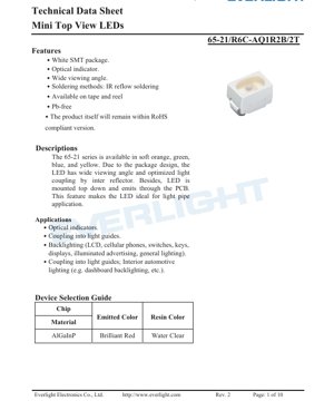
The 65-21 series represents a family of compact, surface-mount, top-view light-emitting diodes (LEDs). These components are designed for applications requiring a wide viewing angle and efficient light coupling. The primary model described in this document emits a brilliant red color, achieved using an AlGaInP semiconductor chip encapsulated in a water-clear resin. The unique package design features a top-down mounting orientation where light is emitted through the printed circuit board (PCB), making it particularly suitable for use with light pipes and waveguides.
Key advantages of this series include its suitability for automated assembly processes like IR reflow soldering, availability on tape and reel for high-volume production, and compliance with RoHS and Pb-free environmental standards. The wide 120-degree viewing angle ensures good visibility from various angles, which is critical for indicator and backlighting applications.
2. In-Depth Technical Parameter Analysis
2.1 Absolute Maximum Ratings
The device's operational limits are defined under an ambient temperature (Ta) of 25°C. Exceeding these ratings may cause permanent damage.
- Reverse Voltage (VR): 5 V. Applying a reverse voltage beyond this limit risks junction breakdown.
- Continuous Forward Current (IF): 50 mA. This is the maximum DC current the LED can handle continuously.
- Peak Forward Current (IFP): 100 mA. This pulsed current rating (at 1/10 duty cycle, 1 kHz) allows for brief over-current conditions, useful for multiplexing or brightness pulsing.
- Power Dissipation (Pd): 110 mW. This is the maximum power the package can dissipate as heat, calculated from forward voltage and current.
- Electrostatic Discharge (ESD) HBM: 2000 V. This Human Body Model rating indicates a moderate level of ESD sensitivity; proper handling precautions are necessary.
- Operating Temperature (Topr): -40°C to +85°C. The device is rated for industrial temperature ranges.
- Storage Temperature (Tstg): -40°C to +90°C.
- Soldering Temperature: For reflow soldering, a peak temperature of 260°C for 10 seconds is specified. For hand soldering, 350°C for 3 seconds is the limit.
2.2 Electro-Optical Characteristics
Performance is measured at Ta=25°C and a standard test current (IF) of 20 mA.
- Luminous Intensity (Iv): Ranges from a minimum of 72 mcd to a maximum of 180 mcd, with a typical value within this range. A tolerance of ±11% applies.
- Viewing Angle (2θ1/2): 120 degrees (typical). This is the full angle at which luminous intensity drops to half its peak value.
- Peak Wavelength (λp): 632 nm (typical). This is the wavelength at which the spectral power distribution is maximum.
- Dominant Wavelength (λd): Ranges from 616.5 nm to 634.5 nm, with a tolerance of ±1 nm. This defines the perceived color (brilliant red).
- Spectral Bandwidth (Δλ): 20 nm (typical). This is the width of the emitted spectrum at half its maximum power.
- Forward Voltage (VF): Ranges from 1.75 V to 2.35 V at 20mA, with a tolerance of ±0.1 V.
- Reverse Current (IR): Maximum of 10 μA when a reverse voltage of 5V is applied.
3. Binning System Explanation
To ensure color and brightness consistency in production, LEDs are sorted into bins based on key parameters.
3.1 Dominant Wavelength Binning (Group A)
This defines the color point. Bins are labeled E4 through E7, each covering a 6 nm range (e.g., E4: 616.5-622.5 nm, E5: 620.5-626.5 nm). This allows designers to select LEDs with very specific red hues for their application.
3.2 Luminous Intensity Binning
This defines the brightness output. Bins are Q1 (72-90 mcd), Q2 (90-112 mcd), R1 (112-140 mcd), and R2 (140-180 mcd). Higher bin codes indicate higher brightness.
3.3 Forward Voltage Binning (Group B)
This groups LEDs by their electrical characteristics. Bins are 0 (1.75-1.95 V), 1 (1.95-2.15 V), and 2 (2.15-2.35 V). Matching voltage bins can simplify current-limiting resistor design in parallel circuits.
4. Performance Curve Analysis
The datasheet provides several characteristic curves essential for design.
4.1 Forward Current vs. Forward Voltage (I-V Curve)
The curve shows the exponential relationship typical of a diode. At the recommended 20 mA operating point, the forward voltage falls within the 1.75V-2.35V binning range. Designers must use a series resistor or constant current driver to limit current, as a small increase in voltage can cause a large, potentially destructive increase in current.
4.2 Relative Luminous Intensity vs. Forward Current
This curve shows that light output increases approximately linearly with current up to the maximum rated continuous current. Operating above 20mA will yield higher brightness but also increases power dissipation and junction temperature, which affects longevity.
4.3 Relative Luminous Intensity vs. Ambient Temperature
Luminous intensity decreases as ambient temperature rises. The curve shows the derating, which is crucial for applications operating in elevated temperature environments. The LED's output is specified at 25°C; at 85°C, the output will be significantly lower.
4.4 Forward Current Derating Curve
This graph defines the maximum allowable continuous forward current as a function of ambient temperature. As temperature increases, the maximum safe current decreases to prevent overheating. At 85°C, the maximum current is lower than the 50mA absolute maximum rating at 25°C.
4.5 Spectral Distribution
The spectrum is a narrow Gaussian-like curve centered around 632 nm (peak) with a 20 nm bandwidth, confirming the monochromatic brilliant red emission.
4.6 Radiation Pattern
The polar diagram illustrates the 120-degree viewing angle. The intensity distribution is relatively Lambertian (cosine-like), providing uniform appearance across the wide viewing cone, which is ideal for indicators.
5. Mechanical and Packaging Information
5.1 Package Outline Dimensions
The SMD package has specific length, width, and height dimensions (in millimeters) with typical tolerances of ±0.1mm unless otherwise noted. The drawing details the top-view shape, side profile, and recommended PCB land pattern (footprint) for soldering.
5.2 Polarity Identification
The cathode is typically marked, often by a notch, a green marking, or a different pad size on the package bottom. Correct polarity must be observed during assembly.
5.3 Tape and Reel Specifications
The component is supplied on carrier tape for automated pick-and-place machines. Key dimensions include pocket size (to hold the LED), tape width, pitch (distance between pockets), and reel diameter. The standard reel contains 2000 pieces.
5.4 Moisture-Resistant Packaging
The reels are sealed in aluminum moisture-proof bags with desiccant to prevent moisture absorption, which is critical for preventing "popcorning" (package cracking) during reflow soldering.
6. Soldering and Assembly Guidelines
6.1 Reflow Soldering Profile
The recommended profile includes a preheat stage, a soak zone, a reflow zone with a peak temperature not exceeding 260°C for 10 seconds, and a controlled cooling stage. The profile must comply with the maximum Tsol rating.
6.2 Hand Soldering
If hand soldering is necessary, the iron tip temperature should not exceed 350°C, and contact time should be limited to 3 seconds per pad. Use a heat sink if possible.
6.3 Storage and Handling Precautions
- ESD Protection: Use grounded workstations and wrist straps.
- Moisture Sensitivity: Do not open the moisture-proof bag until ready for use. If the bag is opened, use the components within the specified floor life or rebake them according to appropriate procedures.
- Storage Conditions: Store unopened bags at 30°C or less and 90% relative humidity or lower.
7. Application Notes and Design Considerations
7.1 Typical Application Scenarios
- Optical Indicators: Status lights on consumer electronics, industrial equipment, and automotive dashboards.
- Light Pipe/Guide Coupling: The top-view, through-PCB emission is ideal for injecting light into acrylic or polycarbonate light guides for button backlighting or panel illumination.
- Backlighting: For LCDs, keypads, switches, and membrane panels.
- General Decorative Lighting: In signage, accent lighting, and illuminated advertising.
- Interior Automotive Lighting: Dashboard backlighting, switch illumination, etc.
7.2 Critical Design Considerations
- Current Limiting is Mandatory: An external series resistor or constant-current driver MUST be used. The forward voltage has a tolerance and a negative temperature coefficient, meaning it decreases as the junction heats up. Without current limiting, thermal runaway can occur, leading to rapid failure.
- Thermal Management: While the package is small, power dissipation (up to 110mW) generates heat. Ensure adequate PCB copper area (thermal relief pads) to conduct heat away, especially when operating at high currents or in hot environments.
- Optical Design: For light pipe applications, the distance between the LED and the light guide entry point, as well as the geometry of the guide, must be optimized to maximize coupling efficiency.
- Binning for Consistency: For applications requiring uniform color and brightness across multiple LEDs, specify tight bins (e.g., a single Dominant Wavelength bin and Luminous Intensity bin).
8. Technical Comparison and Differentiation
The 65-21 series differentiates itself through its specific combination of attributes:
- vs. Standard Side-View LEDs: The top-view, through-PCB emission is a distinct advantage for light pipe applications, as it allows the LED to be mounted flat on the board directly under the guide, simplifying mechanical design.
- vs. Narrow-Angle LEDs: The 120-degree viewing angle offers much wider visibility, making it superior for front-panel indicators where the viewing position is not fixed.
- vs. Non-Automatable Packages: The SMT package and tape-and-reel availability make it highly suitable for modern, high-speed, automated assembly lines, reducing manufacturing cost compared to through-hole LEDs.
9. Frequently Asked Questions (Based on Technical Parameters)
Q: Can I drive this LED directly from a 3.3V or 5V logic supply?
A: No. You must always use a series current-limiting resistor. The resistor value is calculated as R = (Vsupply - VF) / IF. Use the maximum VF from the datasheet (2.35V) for a conservative design to ensure current does not exceed 20mA.
Q: What happens if I operate the LED at 30mA instead of 20mA?
A: The luminous intensity will be higher, but power dissipation and junction temperature will increase. You must check the derating curve to ensure 30mA is safe at your maximum ambient temperature. Long-term reliability may be reduced.
Q: How do I interpret the part number/code for ordering?
A: The code (e.g., from label explanation: CAT/HUE/REF) specifies the Binning selections. You would order based on your required Luminous Intensity (CAT), Dominant Wavelength (HUE), and Forward Voltage (REF) bins.
Q: Is a heat sink required?
A: Typically not for a single LED at 20mA. However, if multiple LEDs are placed close together or operated at high currents/ambient temperatures, the collective heat may require thermal management on the PCB.
10. Practical Design Example
Scenario: Designing a status indicator for a device powered by a 5V rail. The LED should be driven at the standard 20mA.
- Calculate Series Resistor: Using a typical VF of 2.0V for estimation: R = (5V - 2.0V) / 0.020A = 150 Ω. For robustness against VF variation, use the minimum VF (1.75V) to calculate maximum current: Imax = (5V - 1.75V) / 150Ω ≈ 21.7mA, which is safe. A standard 150Ω, 1/10W resistor is suitable.
- PCB Layout: Place the LED according to the recommended land pattern. Include some copper area around the pads for heat dissipation. Ensure polarity marking on the silkscreen matches the LED's cathode indicator.
- Optical Interface: If using a light pipe, model the distance and alignment. A small air gap or use of a transparent silicone gel can improve light coupling efficiency.
11. Operating Principle
This LED is based on an AlGaInP (Aluminum Gallium Indium Phosphide) semiconductor chip. When a forward voltage exceeding the diode's junction potential is applied, electrons and holes are injected into the active region where they recombine. In AlGaInP materials, this recombination releases energy primarily in the form of photons in the red to amber portion of the visible spectrum (approximately 590-650 nm). The specific composition of the AlGaInP layers determines the dominant wavelength, which is 632 nm for this brilliant red variant. The water-clear epoxy resin encapsulant protects the chip, provides mechanical stability, and shapes the light output beam to achieve the wide 120-degree viewing angle.
12. Technology Trends
Miniature top-view SMD LEDs like the 65-21 series are part of a broader trend in optoelectronics towards miniaturization, higher efficiency, and greater integration with automated manufacturing. Key ongoing developments in the industry that influence such components include:
- Increased Efficiency: Ongoing material science improvements aim to produce more lumens per watt (higher efficacy) from the same chip size, allowing for brighter output or lower power consumption.
- Improved Color Consistency: Advances in epitaxial growth and binning processes continue to tighten the tolerances on dominant wavelength and luminous intensity, providing designers with more uniform light sources.
- Enhanced Reliability: Research into better encapsulant materials and packaging techniques leads to longer operational lifetimes and improved resistance to thermal cycling, humidity, and other environmental stresses.
- Integration with Drivers: A market trend is the integration of control circuitry (constant current drivers, PWM controllers) directly into LED packages, simplifying end-user circuit design.
LED Specification Terminology
Complete explanation of LED technical terms
Photoelectric Performance
| Term | Unit/Representation | Simple Explanation | Why Important |
|---|---|---|---|
| Luminous Efficacy | lm/W (lumens per watt) | Light output per watt of electricity, higher means more energy efficient. | Directly determines energy efficiency grade and electricity cost. |
| Luminous Flux | lm (lumens) | Total light emitted by source, commonly called "brightness". | Determines if the light is bright enough. |
| Viewing Angle | ° (degrees), e.g., 120° | Angle where light intensity drops to half, determines beam width. | Affects illumination range and uniformity. |
| CCT (Color Temperature) | K (Kelvin), e.g., 2700K/6500K | Warmth/coolness of light, lower values yellowish/warm, higher whitish/cool. | Determines lighting atmosphere and suitable scenarios. |
| CRI / Ra | Unitless, 0–100 | Ability to render object colors accurately, Ra≥80 is good. | Affects color authenticity, used in high-demand places like malls, museums. |
| SDCM | MacAdam ellipse steps, e.g., "5-step" | Color consistency metric, smaller steps mean more consistent color. | Ensures uniform color across same batch of LEDs. |
| Dominant Wavelength | nm (nanometers), e.g., 620nm (red) | Wavelength corresponding to color of colored LEDs. | Determines hue of red, yellow, green monochrome LEDs. |
| Spectral Distribution | Wavelength vs intensity curve | Shows intensity distribution across wavelengths. | Affects color rendering and quality. |
Electrical Parameters
| Term | Symbol | Simple Explanation | Design Considerations |
|---|---|---|---|
| Forward Voltage | Vf | Minimum voltage to turn on LED, like "starting threshold". | Driver voltage must be ≥Vf, voltages add up for series LEDs. |
| Forward Current | If | Current value for normal LED operation. | Usually constant current drive, current determines brightness & lifespan. |
| Max Pulse Current | Ifp | Peak current tolerable for short periods, used for dimming or flashing. | Pulse width & duty cycle must be strictly controlled to avoid damage. |
| Reverse Voltage | Vr | Max reverse voltage LED can withstand, beyond may cause breakdown. | Circuit must prevent reverse connection or voltage spikes. |
| Thermal Resistance | Rth (°C/W) | Resistance to heat transfer from chip to solder, lower is better. | High thermal resistance requires stronger heat dissipation. |
| ESD Immunity | V (HBM), e.g., 1000V | Ability to withstand electrostatic discharge, higher means less vulnerable. | Anti-static measures needed in production, especially for sensitive LEDs. |
Thermal Management & Reliability
| Term | Key Metric | Simple Explanation | Impact |
|---|---|---|---|
| Junction Temperature | Tj (°C) | Actual operating temperature inside LED chip. | Every 10°C reduction may double lifespan; too high causes light decay, color shift. |
| Lumen Depreciation | L70 / L80 (hours) | Time for brightness to drop to 70% or 80% of initial. | Directly defines LED "service life". |
| Lumen Maintenance | % (e.g., 70%) | Percentage of brightness retained after time. | Indicates brightness retention over long-term use. |
| Color Shift | Δu′v′ or MacAdam ellipse | Degree of color change during use. | Affects color consistency in lighting scenes. |
| Thermal Aging | Material degradation | Deterioration due to long-term high temperature. | May cause brightness drop, color change, or open-circuit failure. |
Packaging & Materials
| Term | Common Types | Simple Explanation | Features & Applications |
|---|---|---|---|
| Package Type | EMC, PPA, Ceramic | Housing material protecting chip, providing optical/thermal interface. | EMC: good heat resistance, low cost; Ceramic: better heat dissipation, longer life. |
| Chip Structure | Front, Flip Chip | Chip electrode arrangement. | Flip chip: better heat dissipation, higher efficacy, for high-power. |
| Phosphor Coating | YAG, Silicate, Nitride | Covers blue chip, converts some to yellow/red, mixes to white. | Different phosphors affect efficacy, CCT, and CRI. |
| Lens/Optics | Flat, Microlens, TIR | Optical structure on surface controlling light distribution. | Determines viewing angle and light distribution curve. |
Quality Control & Binning
| Term | Binning Content | Simple Explanation | Purpose |
|---|---|---|---|
| Luminous Flux Bin | Code e.g., 2G, 2H | Grouped by brightness, each group has min/max lumen values. | Ensures uniform brightness in same batch. |
| Voltage Bin | Code e.g., 6W, 6X | Grouped by forward voltage range. | Facilitates driver matching, improves system efficiency. |
| Color Bin | 5-step MacAdam ellipse | Grouped by color coordinates, ensuring tight range. | Guarantees color consistency, avoids uneven color within fixture. |
| CCT Bin | 2700K, 3000K etc. | Grouped by CCT, each has corresponding coordinate range. | Meets different scene CCT requirements. |
Testing & Certification
| Term | Standard/Test | Simple Explanation | Significance |
|---|---|---|---|
| LM-80 | Lumen maintenance test | Long-term lighting at constant temperature, recording brightness decay. | Used to estimate LED life (with TM-21). |
| TM-21 | Life estimation standard | Estimates life under actual conditions based on LM-80 data. | Provides scientific life prediction. |
| IESNA | Illuminating Engineering Society | Covers optical, electrical, thermal test methods. | Industry-recognized test basis. |
| RoHS / REACH | Environmental certification | Ensures no harmful substances (lead, mercury). | Market access requirement internationally. |
| ENERGY STAR / DLC | Energy efficiency certification | Energy efficiency and performance certification for lighting. | Used in government procurement, subsidy programs, enhances competitiveness. |