Table of Contents
- 1. Product Overview
- 1.1 Core Advantages
- 1.2 Target Market
- 2. In-Depth Technical Parameter Analysis
- 2.1 Photometric and Electrical Characteristics
- 2.2 Absolute Maximum Ratings and Thermal Management
- 3. Performance Curve Analysis
- 3.1 IV Curve and Relative Intensity
- 3.2 Temperature Dependence
- 3.3 Spectral Distribution and Radiation Patterns
- 4. Mechanical and Package Information
- 4.1 Package Dimensions
- 4.2 Recommended Soldering Pad and Polarity
- 5. Soldering and Assembly Guidelines
- 5.1 Reflow Soldering Profile
- 5.2 Precautions for Use
- 6. Application Suggestions and Design Considerations
- 6.1 Typical Application Circuits
- 6.2 Thermal Design Considerations
- 6.3 Optical Design Considerations
- 7. Frequently Asked Questions (Based on Technical Parameters)
- 7.1 How do I achieve white light with this RGB LED?
- 7.2 Can I drive this LED at higher than 20mA for more brightness?
- 7.3 Is a heatsink required?
- 8. Operating Principle and Technology Trends
- 8.1 Basic Operating Principle
- 8.2 Industry Trends
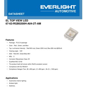
1. Product Overview
This document details the specifications for a high-performance, surface-mount RGB (Red, Green, Blue) LED in a PLCC-6 package. The device is engineered to deliver vibrant color mixing with a wide 120-degree viewing angle, making it suitable for applications requiring uniform illumination. A key feature is its qualification to the AEC-Q102 standard, indicating its robustness and reliability for use in the demanding automotive environment. The product adheres to major environmental and safety regulations, including RoHS, EU REACH, and halogen-free requirements.
1.1 Core Advantages
- Automotive Grade: Qualified to AEC-Q102, ensuring performance under harsh automotive conditions.
- High Luminous Intensity: Offers high brightness levels, particularly in the green channel (Typ. 2200 mcd).
- Wide Viewing Angle: 120-degree viewing angle provides broad and even light distribution.
- Environmental Compliance: Compliant with RoHS, REACH, and halogen-free standards (Br/Cl < 900 ppm, Br+Cl < 1500 ppm).
- Robust Construction: Features Corrosion Robustness Class B1 and good ESD protection (2kV for Red, 8kV for Green/Blue).
1.2 Target Market
The primary application for this LED is in automotive interior lighting, such as dashboard backlighting, switch illumination, and ambient lighting systems. Its characteristics also make it suitable for general decorative and indicator lighting where reliable color performance is required.
2. In-Depth Technical Parameter Analysis
The following section provides a detailed, objective interpretation of the key electrical, optical, and thermal parameters specified in the datasheet.
2.1 Photometric and Electrical Characteristics
The typical operating condition for the specified parameters is at a forward current (IF) of 20mA and an ambient temperature of 25°C.
- Forward Voltage (VF): The voltage drop across each diode at 20mA is typical 1.95V (Red), 2.75V (Green), and 3.00V (Blue). Designers must account for these differences when designing current-limiting circuits for each color channel to ensure balanced brightness and color accuracy.
- Luminous Intensity (IV): The typical output is 900 mcd (Red), 2200 mcd (Green), and 280 mcd (Blue). The significant variation in output between colors necessitates careful driver design or pulse-width modulation (PWM) control to achieve desired white points or specific color hues.
- Dominant Wavelength (λd): Defines the perceived color. Typical values are 623nm (Red), 527nm (Green), and 455nm (Blue). A tolerance of ±1nm is specified, which is tight and beneficial for color consistency in production.
- Viewing Angle (φ): Defined as the off-axis angle where intensity is half the peak value. The 120° specification (±5° tolerance) indicates a very wide, Lambertian-like emission pattern ideal for area lighting.
2.2 Absolute Maximum Ratings and Thermal Management
Operating beyond these limits may cause permanent damage.
- Forward Current (IF): Absolute maximum is 50mA (Red) and 30mA (Green/Blue). The recommended operating current is 20mA. Derating curves are provided and must be followed as the solder pad temperature (TS) increases.
- Power Dissipation (Pd): Maximum ratings are 137mW (Red) and 105mW (Green/Blue). This is calculated as VF * IF. Exceeding this limit risks overheating.
- Junction Temperature (TJ): The maximum allowable temperature at the semiconductor junction is 125°C.
- Thermal Resistance (Rth JS): This parameter, both real and electrical, indicates how effectively heat travels from the junction to the solder point. Lower values are better. The specified max values (e.g., 160 K/W for Red) inform the necessary PCB thermal design (copper area, vias) to maintain a low TJ.
3. Performance Curve Analysis
The graphs in the datasheet provide critical insights into the device's behavior under varying conditions.
3.1 IV Curve and Relative Intensity
The Forward Current vs. Forward Voltage graph shows the exponential relationship typical of diodes. The curves for Red, Green, and Blue are distinct, confirming the different VF values. The Relative Luminous Intensity vs. Forward Current graph is nearly linear up to the typical 20mA point, beyond which efficiency may drop (efficiency droop), especially for the Green and Blue LEDs.
3.2 Temperature Dependence
The Relative Luminous Intensity vs. Junction Temperature graph shows that light output decreases as temperature rises. The Red LED is most sensitive to temperature changes. The Relative Forward Voltage vs. Junction Temperature graph shows VF has a negative temperature coefficient, decreasing by approximately 2mV/°C. This is important for constant-current drivers. The Relative Wavelength Shift vs. Junction Temperature graph indicates the dominant wavelength shifts with temperature (typically 0.1-0.3 nm/°C), which can affect color point stability in precision applications.
3.3 Spectral Distribution and Radiation Patterns
The Relative Spectral Distribution graph shows the narrow emission peaks characteristic of modern LEDs. The Typical Diagram Characteristics of Radiation for each color visually confirms the 120° viewing angle with a smooth, rounded intensity profile.
4. Mechanical and Package Information
4.1 Package Dimensions
The device uses a standard PLCC-6 (Plastic Leaded Chip Carrier) surface-mount package. The mechanical drawing specifies the exact length, width, height, and lead spacing. This information is crucial for PCB footprint design, ensuring proper placement and soldering.
4.2 Recommended Soldering Pad and Polarity
A land pattern recommendation is provided to ensure reliable solder joints and mechanical stability. The pinout diagram identifies the anode and cathode for each of the three LED chips (Red, Green, Blue) and the common cathode configuration, which is essential for correct circuit connection.
5. Soldering and Assembly Guidelines
5.1 Reflow Soldering Profile
The datasheet specifies a reflow profile with a peak temperature of 260°C for a maximum of 30 seconds. This is a standard lead-free (Pb-free) reflow profile. Adherence to this profile is necessary to prevent thermal damage to the plastic package or the LED die.
5.2 Precautions for Use
- ESD Handling: Although the device has built-in ESD protection (2kV/8kV HBM), standard ESD precautions should be followed during handling and assembly.
- Current Control: LEDs must be driven with a constant current source, not a constant voltage, to prevent thermal runaway.
- Storage: The Moisture Sensitivity Level (MSL) is 3. This means the device must be baked before soldering if the packaging has been opened and exposed to ambient humidity for longer than the specified time (typically 168 hours).
6. Application Suggestions and Design Considerations
6.1 Typical Application Circuits
For automotive 12V systems, a typical circuit involves a voltage regulator (e.g., to 5V or 3.3V) followed by separate constant-current drivers or current-limiting resistors for each RGB channel. Using PWM control from a microcontroller is the standard method for dynamic color mixing and dimming.
6.2 Thermal Design Considerations
Given the thermal resistance and power dissipation, the PCB must act as a heat sink. This involves using adequate copper pour connected to the thermal pad of the LED footprint, and potentially thermal vias to inner or bottom layers to spread heat. Failure to manage heat will reduce light output, shift color, and shorten lifespan.
6.3 Optical Design Considerations
The 120° viewing angle often eliminates the need for secondary optics in ambient lighting. For more focused light, external lenses or light guides may be used. The different intensities of the three colors must be calibrated in software/firmware to achieve a target white point (e.g., D65).
7. Frequently Asked Questions (Based on Technical Parameters)
7.1 How do I achieve white light with this RGB LED?
White light is created by mixing the three primary colors at specific intensity ratios. Due to the different luminous efficiencies (Green is brightest, Blue is dimmest at 20mA), you cannot simply drive all three channels at the same current. You must calibrate the drive currents or PWM duty cycles. For example, you might drive the Red at 20mA, the Green at a lower current or duty cycle, and the Blue at 20mA or higher, adjusting until the desired white chromaticity is achieved on a target.
7.2 Can I drive this LED at higher than 20mA for more brightness?
You can, but you must strictly consult the Forward Current Derating Curves. As the solder pad temperature rises, the maximum allowable current decreases. For example, the Red LED's absolute max is 50mA, but this is only allowed when the solder pad is at or below 103°C. At 110°C, the maximum current is only 35mA. Exceeding these limits will overheat the junction, causing rapid degradation.
7.3 Is a heatsink required?
A dedicated metal heatsink is not typically required for a single LED at 20mA in a PLCC-6 package. However, a well-designed PCB thermal pad is absolutely necessary and acts as the primary heatsink. For arrays of LEDs or operation in high ambient temperatures, additional thermal management must be evaluated based on the total power dissipation and thermal resistance path.
8. Operating Principle and Technology Trends
8.1 Basic Operating Principle
An LED is a semiconductor diode. When a forward voltage exceeding its bandgap energy is applied, electrons recombine with holes in the active region, releasing energy in the form of photons (light). The color (wavelength) of the light is determined by the bandgap energy of the semiconductor materials used (e.g., AlInGaP for Red, InGaN for Green and Blue). The PLCC package incorporates the LED die, a reflective cavity, and a transparent epoxy lens that shapes the light output.
8.2 Industry Trends
The market for automotive LEDs continues to grow, driven by interior ambient lighting, exterior signaling, and advanced applications like pixelated headlights. Trends include:
- Higher Efficiency: Ongoing development aims to increase lumens per watt (lm/W), reducing energy consumption and thermal load.
- Improved Color Consistency: Tighter binning of wavelength and flux to ensure uniform appearance in multi-LED applications.
- Advanced Packaging: Development of packages with lower thermal resistance and higher optical extraction efficiency.
- Integrated Solutions: Growth of LED modules with integrated drivers and controllers, simplifying design for automotive tier-1 suppliers.
This PLCC-6 RGB LED represents a mature, reliable solution that aligns with the core requirements of current automotive lighting designs, emphasizing reliability, regulatory compliance, and performance.
LED Specification Terminology
Complete explanation of LED technical terms
Photoelectric Performance
| Term | Unit/Representation | Simple Explanation | Why Important |
|---|---|---|---|
| Luminous Efficacy | lm/W (lumens per watt) | Light output per watt of electricity, higher means more energy efficient. | Directly determines energy efficiency grade and electricity cost. |
| Luminous Flux | lm (lumens) | Total light emitted by source, commonly called "brightness". | Determines if the light is bright enough. |
| Viewing Angle | ° (degrees), e.g., 120° | Angle where light intensity drops to half, determines beam width. | Affects illumination range and uniformity. |
| CCT (Color Temperature) | K (Kelvin), e.g., 2700K/6500K | Warmth/coolness of light, lower values yellowish/warm, higher whitish/cool. | Determines lighting atmosphere and suitable scenarios. |
| CRI / Ra | Unitless, 0–100 | Ability to render object colors accurately, Ra≥80 is good. | Affects color authenticity, used in high-demand places like malls, museums. |
| SDCM | MacAdam ellipse steps, e.g., "5-step" | Color consistency metric, smaller steps mean more consistent color. | Ensures uniform color across same batch of LEDs. |
| Dominant Wavelength | nm (nanometers), e.g., 620nm (red) | Wavelength corresponding to color of colored LEDs. | Determines hue of red, yellow, green monochrome LEDs. |
| Spectral Distribution | Wavelength vs intensity curve | Shows intensity distribution across wavelengths. | Affects color rendering and quality. |
Electrical Parameters
| Term | Symbol | Simple Explanation | Design Considerations |
|---|---|---|---|
| Forward Voltage | Vf | Minimum voltage to turn on LED, like "starting threshold". | Driver voltage must be ≥Vf, voltages add up for series LEDs. |
| Forward Current | If | Current value for normal LED operation. | Usually constant current drive, current determines brightness & lifespan. |
| Max Pulse Current | Ifp | Peak current tolerable for short periods, used for dimming or flashing. | Pulse width & duty cycle must be strictly controlled to avoid damage. |
| Reverse Voltage | Vr | Max reverse voltage LED can withstand, beyond may cause breakdown. | Circuit must prevent reverse connection or voltage spikes. |
| Thermal Resistance | Rth (°C/W) | Resistance to heat transfer from chip to solder, lower is better. | High thermal resistance requires stronger heat dissipation. |
| ESD Immunity | V (HBM), e.g., 1000V | Ability to withstand electrostatic discharge, higher means less vulnerable. | Anti-static measures needed in production, especially for sensitive LEDs. |
Thermal Management & Reliability
| Term | Key Metric | Simple Explanation | Impact |
|---|---|---|---|
| Junction Temperature | Tj (°C) | Actual operating temperature inside LED chip. | Every 10°C reduction may double lifespan; too high causes light decay, color shift. |
| Lumen Depreciation | L70 / L80 (hours) | Time for brightness to drop to 70% or 80% of initial. | Directly defines LED "service life". |
| Lumen Maintenance | % (e.g., 70%) | Percentage of brightness retained after time. | Indicates brightness retention over long-term use. |
| Color Shift | Δu′v′ or MacAdam ellipse | Degree of color change during use. | Affects color consistency in lighting scenes. |
| Thermal Aging | Material degradation | Deterioration due to long-term high temperature. | May cause brightness drop, color change, or open-circuit failure. |
Packaging & Materials
| Term | Common Types | Simple Explanation | Features & Applications |
|---|---|---|---|
| Package Type | EMC, PPA, Ceramic | Housing material protecting chip, providing optical/thermal interface. | EMC: good heat resistance, low cost; Ceramic: better heat dissipation, longer life. |
| Chip Structure | Front, Flip Chip | Chip electrode arrangement. | Flip chip: better heat dissipation, higher efficacy, for high-power. |
| Phosphor Coating | YAG, Silicate, Nitride | Covers blue chip, converts some to yellow/red, mixes to white. | Different phosphors affect efficacy, CCT, and CRI. |
| Lens/Optics | Flat, Microlens, TIR | Optical structure on surface controlling light distribution. | Determines viewing angle and light distribution curve. |
Quality Control & Binning
| Term | Binning Content | Simple Explanation | Purpose |
|---|---|---|---|
| Luminous Flux Bin | Code e.g., 2G, 2H | Grouped by brightness, each group has min/max lumen values. | Ensures uniform brightness in same batch. |
| Voltage Bin | Code e.g., 6W, 6X | Grouped by forward voltage range. | Facilitates driver matching, improves system efficiency. |
| Color Bin | 5-step MacAdam ellipse | Grouped by color coordinates, ensuring tight range. | Guarantees color consistency, avoids uneven color within fixture. |
| CCT Bin | 2700K, 3000K etc. | Grouped by CCT, each has corresponding coordinate range. | Meets different scene CCT requirements. |
Testing & Certification
| Term | Standard/Test | Simple Explanation | Significance |
|---|---|---|---|
| LM-80 | Lumen maintenance test | Long-term lighting at constant temperature, recording brightness decay. | Used to estimate LED life (with TM-21). |
| TM-21 | Life estimation standard | Estimates life under actual conditions based on LM-80 data. | Provides scientific life prediction. |
| IESNA | Illuminating Engineering Society | Covers optical, electrical, thermal test methods. | Industry-recognized test basis. |
| RoHS / REACH | Environmental certification | Ensures no harmful substances (lead, mercury). | Market access requirement internationally. |
| ENERGY STAR / DLC | Energy efficiency certification | Energy efficiency and performance certification for lighting. | Used in government procurement, subsidy programs, enhances competitiveness. |