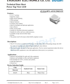
1. Product Overview
The 67-31A series represents a family of Power Top View LEDs designed in a compact P-LCC-3 surface-mount package. This device is engineered to deliver high flux output with a wide viewing angle, making it particularly suitable for applications requiring uniform illumination and indicator functions. The series is available in soft orange, red, and yellow color variants, with the specific model detailed in this document featuring a blue InGaN chip encapsulated in a colorless clear resin.
The core advantages of this LED series include its high current capability, robust construction suitable for automatic placement, and compatibility with both reflow and wave soldering processes. Its design incorporates an inter-reflector which optimizes light coupling efficiency, a critical feature for light pipe and backlight applications. The low current requirement further enhances its suitability for portable electronic devices where power efficiency is paramount.
2. Technical Parameter Deep-Dive Analysis
2.1 Absolute Maximum Ratings
The device is specified to operate reliably within the following absolute maximum limits, measured at an ambient temperature (TA) of 25°C. Exceeding these ratings may cause permanent damage.
- Reverse Voltage (VR): 5 V - The maximum voltage that can be applied in the reverse direction across the LED terminals.
- Forward Current (IF): 30 mA - The maximum continuous DC forward current recommended for normal operation.
- Peak Forward Current (IFP): 100 mA - The maximum allowable pulsed forward current, specified under a duty cycle of 1/10 at 1 kHz.
- Power Dissipation (Pd): 110 mW - The maximum power the device can dissipate.
- Electrostatic Discharge (ESD) HBM: 150 V - The Human Body Model ESD withstand voltage, indicating a sensitivity that requires standard ESD handling precautions.
- Operating Temperature (Topr): -40°C to +85°C - The ambient temperature range for reliable operation.
- Storage Temperature (Tstg): -40°C to +90°C - The temperature range for safe storage.
- Soldering Temperature (Tsol): Reflow: 260°C for 10 seconds max; Hand Soldering: 350°C for 3 seconds max.
2.2 Electro-Optical Characteristics
The key performance parameters are defined under a standard test condition of IF = 30 mA and TA = 25°C, unless otherwise stated.
- Luminous Intensity (IV): Ranges from a minimum of 285 mcd to a maximum of 715 mcd. The typical value is not specified, indicating performance is managed through a binning system.
- Viewing Angle (2θ1/2): 120° (typical). This wide viewing angle is a defining feature, enabled by the package design and inter-reflector, ensuring broad and even light distribution.
- Peak Wavelength (λP): 468 nm (typical). This is the wavelength at which the spectral power distribution is maximum.
- Dominant Wavelength (λd): 464.5 nm to 476.5 nm. This is the single wavelength perceived by the human eye, equivalent to the color of the emitted light. A tolerance of ±1 nm is applied.
- Spectral Bandwidth (Δλ): 35 nm (typical). This defines the width of the emitted spectrum at half its maximum power (FWHM).
- Forward Voltage (VF): 2.75 V to 3.95 V. The voltage drop across the LED when driven at 30 mA. A tolerance of ±0.1V is noted.
- Reverse Current (IR): 10 μA (max) at VR = 5V.
3. Binning System Explanation
To ensure color and brightness consistency in production, the LEDs are sorted into bins based on three key parameters.
3.1 Dominant Wavelength Binning (Group A)
Defines the precise color (hue) of the LED. Bins are labeled A9 through A12, each covering a 3 nm range within the overall 464.5-476.5 nm specification.
3.2 Luminous Intensity Binning
Defines the brightness output. Bins are labeled T1, T2, U1, and U2, with ascending minimum and maximum mcd values. This allows selection of appropriate brightness for the application.
3.3 Forward Voltage Binning (Group M)
Defines the electrical characteristic. Bins are labeled M5 through M8, each covering a 0.3 V range within the overall 2.75-3.95 V specification. This is useful for circuit design, particularly when driving multiple LEDs in series.
4. Performance Curve Analysis
The datasheet references typical electro-optical characteristic curves. While the specific graphs are not detailed in the provided text, such curves typically include:
- I-V (Current-Voltage) Curve: Shows the relationship between forward voltage (VF) and forward current (IF). It demonstrates the exponential nature of the diode, highlighting the need for current-limiting resistors as the voltage increases beyond the turn-on threshold.
- Relative Luminous Intensity vs. Forward Current: Illustrates how light output increases with drive current, typically in a near-linear relationship within the specified operating range.
- Relative Luminous Intensity vs. Ambient Temperature: Shows the derating of light output as junction temperature increases. This is critical for thermal management in high-power or high-ambient-temperature applications.
- Spectral Power Distribution: A plot of relative intensity versus wavelength, showing the peak at ~468 nm and the 35 nm bandwidth.
5. Mechanical and Packaging Information
5.1 Package Dimensions and Polarity
The LED uses a P-LCC-3 (Plastic Leaded Chip Carrier) package. The dimensional drawing specifies the length, width, height, and lead positions. A polarity indicator (typically a notch or a marked cathode) is clearly shown to ensure correct orientation during assembly. A recommended solder pad footprint design is provided to ensure proper soldering and mechanical stability.
5.2 Reel and Tape Packaging
The device is supplied on tape and reel for automated assembly. The carrier tape dimensions are specified, with a standard loaded quantity of 2000 pieces per reel. Reel dimensions are also provided for handling by pick-and-place machines. The packaging includes moisture-resistant measures: components are packed in an aluminum moisture-proof bag with a desiccant and a humidity indicator card to prevent moisture absorption damage prior to soldering.
6. Soldering and Assembly Guidelines
The LED is rated for standard soldering processes.
- Reflow Soldering: Maximum peak temperature of 260°C for a duration not exceeding 10 seconds.
- Hand Soldering: Iron tip temperature should not exceed 350°C, with contact time limited to 3 seconds per lead.
- Precautions: A critical warning is provided: an external current-limiting resistor MUST be used in series with the LED. The exponential I-V characteristic means a small increase in voltage can cause a large, destructive increase in current. Proper ESD handling procedures should be followed during all stages of handling and assembly.
7. Reliability Testing
The product undergoes a comprehensive suite of reliability tests conducted with a 90% confidence level and 10% Lot Tolerance Percent Defective (LTPD). Key tests include:
- Reflow Soldering Resistance
- Temperature Cycling (-40°C to +100°C)
- Thermal Shock (-10°C to +100°C)
- High-Temperature Storage (100°C)
- Low-Temperature Storage (-40°C)
- DC Operating Life (30 mA, 25°C)
- High Temperature/Humidity (85°C/85% RH)
These tests validate the device's robustness under various environmental and operational stresses.
8. Application Suggestions
8.1 Typical Application Scenarios
- Indicator and Backlight for Consumer Electronics: Audio/video equipment, set-top boxes, gaming consoles.
- Office and Home Equipment: Printers, routers, appliances, control panels.
- Flat Backlighting: For LCDs, membrane switches, and illuminated symbols.
- Light Pipe Applications: The wide viewing angle and inter-reflector design make it ideal for coupling light into plastic light guides for status indication or decorative lighting.
- General Purpose Indication: Any application requiring a bright, reliable, surface-mount status indicator.
8.2 Design Considerations
- Current Limiting: Always use a series resistor. Calculate its value based on the supply voltage (Vcc), the LED's forward voltage (VF - use max value for safety), and the desired forward current (IF). R = (Vcc - VF) / IF.
- Thermal Management: While power dissipation is low, ensure adequate PCB copper area or thermal relief if operating at high ambient temperatures or maximum current to maintain light output and longevity.
- Optical Design: For light pipe applications, the LED should be positioned precisely against the pipe's input surface. The wide viewing angle helps maximize coupling efficiency.
9. Technical Comparison and Differentiation
The 67-31A series differentiates itself through several key features:
- Package: The P-LCC-3 package offers a robust, industry-standard footprint with good thermal and mechanical properties compared to smaller chip LEDs.
- Viewing Angle: The 120° viewing angle is significantly wider than many standard top-view LEDs, which often feature 60-80° angles. This is a major advantage for applications requiring wide-area illumination.
- Inter-Reflector: This integrated optical feature enhances light extraction and directionality, improving efficiency in light pipe and backlight designs compared to LEDs without such a feature.
- Current Capability: A 30 mA continuous current rating provides higher brightness potential compared to low-current indicator LEDs rated for 5-20 mA.
10. Frequently Asked Questions (Based on Technical Parameters)
Q: What resistor value should I use with a 5V supply?
A: Using the maximum VF of 3.95V for a conservative design and IF of 30mA: R = (5V - 3.95V) / 0.03A = 35 Ohms. Use the nearest standard value (e.g., 33 or 39 Ohms) and check power rating.
Q: Can I drive this LED with a PWM signal for dimming?
A: Yes. The LED can be dimmed effectively using PWM. Ensure the peak current in the pulse does not exceed the 100 mA IFP rating and the average current does not exceed 30 mA IF.
Q: How does temperature affect performance?
A: Luminous intensity typically decreases as junction temperature increases. The forward voltage also decreases slightly with rising temperature. For consistent brightness, thermal management and/or optical feedback may be necessary in demanding environments.
Q: What is the difference between Peak and Dominant Wavelength?
A: Peak Wavelength (468 nm) is the physical peak of the light spectrum emitted. Dominant Wavelength (464.5-476.5 nm) is the perceived color by the human eye, calculated from the full spectrum. Dominant wavelength is more relevant for color indication.
11. Practical Use Case Example
Scenario: Designing a status indicator panel for a network router using a light pipe.
1. Selection: Choose a 67-31A LED from the U1 or U2 luminous intensity bin for high visibility. Select a consistent Dominant Wavelength bin (e.g., A10) for uniform color across multiple units.
2. Circuit Design: The router's internal logic runs at 3.3V. Using a typical VF of 3.2V and IF of 20 mA for power saving: R = (3.3V - 3.2V) / 0.02A = 5 Ohms. A 5.1 Ohm resistor would be suitable.
3. Layout: Place the LED on the PCB directly beneath the light pipe's entry point. Follow the recommended solder pad layout for reliability.
4. Result: The wide 120° viewing angle efficiently couples light into the pipe, creating a bright, evenly lit indicator that is clearly visible from various angles, fulfilling the design requirement with a simple, reliable solution.
12. Operating Principle
The LED operates on the principle of electroluminescence in a semiconductor. The core component is an InGaN (Indium Gallium Nitride) chip. When a forward voltage exceeding the diode's turn-on threshold is applied, electrons and holes are injected into the active region of the semiconductor. These charge carriers recombine, releasing energy in the form of photons (light). The specific composition of the InGaN material determines the bandgap energy, which in turn defines the wavelength (color) of the emitted light—in this case, blue. The colorless clear epoxy resin encapsulant protects the chip, acts as a lens to shape the light output, and may contain phosphors if a different color (like the mentioned soft orange, red, yellow) is required, though for the blue version, it remains clear.
13. Technology Trends
The LED industry continues to evolve towards higher efficiency, smaller form factors, and greater integration. Trends relevant to devices like the 67-31A include:
- Increased Efficiency: Ongoing material science improvements aim to produce more lumens per watt (efficacy), allowing for brighter output at the same current or the same brightness with lower power consumption.
- Miniaturization: While the P-LCC-3 is a standard package, there is a parallel trend towards even smaller chip-scale package (CSP) LEDs for space-constrained applications, though often with trade-offs in viewing angle and ease of handling.
- Improved Color Consistency: Advancements in epitaxial growth and binning processes lead to tighter wavelength and intensity distributions, reducing the need for selective binning in high-volume applications.
- Enhanced Reliability: Improvements in packaging materials (epoxy, silicone) and die attach technologies continue to push the boundaries of operating temperature ranges and longevity, especially under high-current or high-temperature conditions.
LED Specification Terminology
Complete explanation of LED technical terms
Photoelectric Performance
| Term | Unit/Representation | Simple Explanation | Why Important |
|---|---|---|---|
| Luminous Efficacy | lm/W (lumens per watt) | Light output per watt of electricity, higher means more energy efficient. | Directly determines energy efficiency grade and electricity cost. |
| Luminous Flux | lm (lumens) | Total light emitted by source, commonly called "brightness". | Determines if the light is bright enough. |
| Viewing Angle | ° (degrees), e.g., 120° | Angle where light intensity drops to half, determines beam width. | Affects illumination range and uniformity. |
| CCT (Color Temperature) | K (Kelvin), e.g., 2700K/6500K | Warmth/coolness of light, lower values yellowish/warm, higher whitish/cool. | Determines lighting atmosphere and suitable scenarios. |
| CRI / Ra | Unitless, 0–100 | Ability to render object colors accurately, Ra≥80 is good. | Affects color authenticity, used in high-demand places like malls, museums. |
| SDCM | MacAdam ellipse steps, e.g., "5-step" | Color consistency metric, smaller steps mean more consistent color. | Ensures uniform color across same batch of LEDs. |
| Dominant Wavelength | nm (nanometers), e.g., 620nm (red) | Wavelength corresponding to color of colored LEDs. | Determines hue of red, yellow, green monochrome LEDs. |
| Spectral Distribution | Wavelength vs intensity curve | Shows intensity distribution across wavelengths. | Affects color rendering and quality. |
Electrical Parameters
| Term | Symbol | Simple Explanation | Design Considerations |
|---|---|---|---|
| Forward Voltage | Vf | Minimum voltage to turn on LED, like "starting threshold". | Driver voltage must be ≥Vf, voltages add up for series LEDs. |
| Forward Current | If | Current value for normal LED operation. | Usually constant current drive, current determines brightness & lifespan. |
| Max Pulse Current | Ifp | Peak current tolerable for short periods, used for dimming or flashing. | Pulse width & duty cycle must be strictly controlled to avoid damage. |
| Reverse Voltage | Vr | Max reverse voltage LED can withstand, beyond may cause breakdown. | Circuit must prevent reverse connection or voltage spikes. |
| Thermal Resistance | Rth (°C/W) | Resistance to heat transfer from chip to solder, lower is better. | High thermal resistance requires stronger heat dissipation. |
| ESD Immunity | V (HBM), e.g., 1000V | Ability to withstand electrostatic discharge, higher means less vulnerable. | Anti-static measures needed in production, especially for sensitive LEDs. |
Thermal Management & Reliability
| Term | Key Metric | Simple Explanation | Impact |
|---|---|---|---|
| Junction Temperature | Tj (°C) | Actual operating temperature inside LED chip. | Every 10°C reduction may double lifespan; too high causes light decay, color shift. |
| Lumen Depreciation | L70 / L80 (hours) | Time for brightness to drop to 70% or 80% of initial. | Directly defines LED "service life". |
| Lumen Maintenance | % (e.g., 70%) | Percentage of brightness retained after time. | Indicates brightness retention over long-term use. |
| Color Shift | Δu′v′ or MacAdam ellipse | Degree of color change during use. | Affects color consistency in lighting scenes. |
| Thermal Aging | Material degradation | Deterioration due to long-term high temperature. | May cause brightness drop, color change, or open-circuit failure. |
Packaging & Materials
| Term | Common Types | Simple Explanation | Features & Applications |
|---|---|---|---|
| Package Type | EMC, PPA, Ceramic | Housing material protecting chip, providing optical/thermal interface. | EMC: good heat resistance, low cost; Ceramic: better heat dissipation, longer life. |
| Chip Structure | Front, Flip Chip | Chip electrode arrangement. | Flip chip: better heat dissipation, higher efficacy, for high-power. |
| Phosphor Coating | YAG, Silicate, Nitride | Covers blue chip, converts some to yellow/red, mixes to white. | Different phosphors affect efficacy, CCT, and CRI. |
| Lens/Optics | Flat, Microlens, TIR | Optical structure on surface controlling light distribution. | Determines viewing angle and light distribution curve. |
Quality Control & Binning
| Term | Binning Content | Simple Explanation | Purpose |
|---|---|---|---|
| Luminous Flux Bin | Code e.g., 2G, 2H | Grouped by brightness, each group has min/max lumen values. | Ensures uniform brightness in same batch. |
| Voltage Bin | Code e.g., 6W, 6X | Grouped by forward voltage range. | Facilitates driver matching, improves system efficiency. |
| Color Bin | 5-step MacAdam ellipse | Grouped by color coordinates, ensuring tight range. | Guarantees color consistency, avoids uneven color within fixture. |
| CCT Bin | 2700K, 3000K etc. | Grouped by CCT, each has corresponding coordinate range. | Meets different scene CCT requirements. |
Testing & Certification
| Term | Standard/Test | Simple Explanation | Significance |
|---|---|---|---|
| LM-80 | Lumen maintenance test | Long-term lighting at constant temperature, recording brightness decay. | Used to estimate LED life (with TM-21). |
| TM-21 | Life estimation standard | Estimates life under actual conditions based on LM-80 data. | Provides scientific life prediction. |
| IESNA | Illuminating Engineering Society | Covers optical, electrical, thermal test methods. | Industry-recognized test basis. |
| RoHS / REACH | Environmental certification | Ensures no harmful substances (lead, mercury). | Market access requirement internationally. |
| ENERGY STAR / DLC | Energy efficiency certification | Energy efficiency and performance certification for lighting. | Used in government procurement, subsidy programs, enhances competitiveness. |