Table of Contents
- 1. Product Overview
- 2. In-Depth Technical Parameter Analysis
- 2.1 Absolute Maximum Ratings
- 2.2 Electro-Optical Characteristics
- 3. Binning System Explanation
- 3.1 Luminous Intensity Binning
- 3.2 Dominant Wavelength Binning
- 3.3 Chromaticity Coordinate Binning (White LED)
- 4. Performance Curve Analysis
- 4.1 Spectral Distribution
- 4.2 Forward Current vs. Forward Voltage (I-V Curve)
- 4.3 Wavelength vs. Forward Current
- 4.4 Relative Intensity vs. Forward Current
- 4.5 Maximum Permissible Forward Current vs. Temperature
- 5. Soldering and Assembly Guidelines
- 6. Application Suggestions and Design Considerations
- 6.1 Typical Application Circuits
- 6.2 Thermal Management
- 6.3 Optical Design
- 7. Technical Comparison and Differentiation
- 8. Frequently Asked Questions (Based on Technical Parameters)
- 9. Practical Design and Usage Case
- 10. Operating Principle Introduction
- 11. Technology Trends and Context
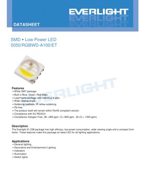
1. Product Overview
This document details the specifications for a compact, surface-mount, low-power LED package in the 5050 form factor. The device integrates four individual semiconductor chips within a single white resin package: Red (R), Green (G), Blue (B), and White (W). This multi-chip configuration enables the generation of a broad spectrum of colors, including pure white light from the dedicated white die and mixed colors from the RGB combination. The package is designed with an 8-pin lead frame, providing individual electrical access to each chip for independent control.
The core advantages of this LED include its high luminous efficacy, low power consumption, and a wide 120-degree viewing angle. Its compact SMD form factor makes it suitable for automated assembly processes like IR reflow soldering. The product is compliant with key environmental and safety standards, including RoHS, EU REACH, and halogen-free requirements (Br <900 ppm, Cl <900 ppm, Br+Cl < 1500 ppm).
The target applications are diverse, leveraging its color-mixing capability and general illumination properties. Primary uses include general decorative and entertainment lighting, status indicators, backlighting or illumination for switches and panels, and other applications where compact, multi-color light sources are required.
2. In-Depth Technical Parameter Analysis
2.1 Absolute Maximum Ratings
All ratings are specified at a soldering point temperature (TSoldering) of 25°C. Exceeding these limits may cause permanent damage.
- Reverse Voltage (VR): 5V maximum for all chips (R, G, B, W). Applying higher reverse voltage can cause junction breakdown.
- Continuous Forward Current (IF): Red and White chips are rated for 200mA. Green and Blue chips are rated for 180mA. These are DC current limits.
- Peak Forward Current (IFP): For pulsed operation with a duty cycle of 1/10 and pulse width of 10ms. Red/White: 400mA. Green/Blue: 360mA.
- Power Dissipation (Pd): The maximum allowable power loss per chip. R: 520mW, G/B: 684mW, W: 720mW. This is critical for thermal management.
- Temperature Ranges: Operating: -40°C to +85°C. Storage: -40°C to +100°C. Maximum Junction Temperature (Tj): 110°C.
- Thermal Resistance (Rth J-S): Junction-to-soldering point. R: 60°C/W, G: 110°C/W, B: 75°C/W, W: 75°C/W. Lower values indicate better heat transfer from the chip to the board.
- Soldering Temperature: IR Reflow: 260°C peak for 10 seconds maximum. Hand Soldering: 350°C for 3 seconds maximum.
2.2 Electro-Optical Characteristics
Typical performance is measured at TSoldering=25°C and IF=100mA, unless otherwise stated.
- Luminous Intensity (Iv): Measured in millicandelas (mcd). Typical values: R: 5000 mcd, G: 11000 mcd, B: 3000 mcd, W: 10000 mcd. Minimum values are also specified. Tolerance is ±11%.
- Forward Voltage (VF): The voltage drop across the LED at 100mA. Typical/Max: R: 2.10V/2.60V, G: 3.00V/3.80V, B: 3.10V/3.80V, W: 2.90V/3.60V. Tolerance is ±0.1V. This parameter is crucial for driver design.
- Viewing Angle (2θ1/2): 120 degrees. This is the full angle at which luminous intensity is half of the peak intensity (on-axis).
- Dominant Wavelength (λp): The peak wavelength of emitted light. R: 619-629nm, G: 520-535nm, B: 460-475nm. Tolerance is ±1nm. The white LED's color is described as "Yellowish".
- Reverse Current (IR): Maximum leakage current of 10µA at VR = -5V for all chips.
3. Binning System Explanation
To ensure color and brightness consistency, LEDs are sorted into bins based on measured performance.
3.1 Luminous Intensity Binning
LEDs are grouped by their measured luminous intensity at IF=100mA. Each bin has a code (e.g., CB, DA, EA) defining a min/max intensity range in mcd.
- Red (R): Bins CB (3550-4500 mcd), DA (4500-5600 mcd), DB (5600-7100 mcd).
- Green (G): Bins EA (7100-9000 mcd), EB (9000-11200 mcd), FA (11200-14000 mcd).
- Blue (B): Bins BA (1800-2240 mcd), BB (2240-2800 mcd), CA (2800-3550 mcd), CB (3550-4500 mcd).
- White (W): Bins DB (5600-7100 mcd), EA (7100-9000 mcd), EB (9000-11200 mcd), FA (11200-14000 mcd), FB (14000-18000 mcd).
3.2 Dominant Wavelength Binning
LEDs are also binned by the peak wavelength of their emitted light to control color hue.
- Red (R): Bins RB (619-624 nm), RC (624-629 nm).
- Green (G): Bins G7 (520-525 nm), G8 (525-530 nm), G9 (530-535 nm).
- Blue (B): Bins B3 (460-465 nm), B4 (465-470 nm), B5 (470-475 nm).
3.3 Chromaticity Coordinate Binning (White LED)
For the white LED, color is precisely defined using chromaticity coordinates (x, y) on the CIE 1931 diagram. The datasheet provides a detailed table of bin codes (e.g., A11, A12, A21) with their corresponding quadrilateral areas defined by four sets of (x,y) coordinates. The tolerance for these coordinates is ±0.01. This system ensures tight control over the white point (e.g., cool white, neutral white, warm white) of the emitted light.
4. Performance Curve Analysis
The datasheet includes typical characteristic curves, which are essential for understanding device behavior under different operating conditions.
4.1 Spectral Distribution
A typical spectral distribution curve is shown, plotting relative intensity against wavelength. This curve visually represents the light output composition. For the RGB chips, it shows narrow peaks at their dominant wavelengths. For the white LED (typically a blue chip with a phosphor coating), the curve shows a broad peak from the phosphor's converted light, combined with a smaller blue peak from the pump LED. The standard human eye response curve (V(λ)) is also referenced for photometric calculations.
4.2 Forward Current vs. Forward Voltage (I-V Curve)
Separate curves for R, G, B, and W chips show the relationship between forward current (IF) and forward voltage (VF) at 25°C. These curves are exponential in nature. They are critical for designing current-limiting circuits or constant-current drivers. The curves confirm that at a typical operating current of 100mA, the VF aligns with the typical values stated in the electrical table.
4.3 Wavelength vs. Forward Current
These curves illustrate how the dominant wavelength (color) of each chip shifts with increasing forward current. Generally, wavelength can increase slightly with current due to junction heating and other effects. This is an important consideration for applications requiring precise color stability across a range of brightness levels.
4.4 Relative Intensity vs. Forward Current
These plots show how the light output (relative luminous intensity for G/W, relative radiometric intensity for R/B) increases with forward current. The relationship is generally linear at lower currents but can saturate at higher currents due to thermal and efficiency droop. This data is used to determine the optimal drive current for a desired brightness level.
4.5 Maximum Permissible Forward Current vs. Temperature
This derating curve is one of the most important for reliability. It shows how the maximum allowable continuous forward current must be reduced as the ambient (or solder point) temperature increases. For example, at 85°C, the permissible current will be significantly lower than the 25°C rating. Operating above this curve risks exceeding the maximum junction temperature, leading to accelerated lumen depreciation and reduced lifespan.
5. Soldering and Assembly Guidelines
The LED is sensitive to electrostatic discharge (ESD) and must be handled with appropriate precautions. The recommended soldering methods are:
- IR Reflow Soldering: This is the preferred method for SMD assembly. The maximum peak temperature should not exceed 260°C, and the time above 260°C should be limited to 10 seconds. A standard lead-free reflow profile is suitable.
- Hand Soldering: If necessary, hand soldering can be performed with an iron tip temperature not exceeding 350°C. The contact time per lead should be limited to 3 seconds to prevent thermal damage to the package and wire bonds.
Care must be taken to avoid mechanical stress on the package during and after soldering. The storage temperature range is -40°C to +100°C.
6. Application Suggestions and Design Considerations
6.1 Typical Application Circuits
Each chip (R, G, B, W) requires its own current-limiting circuit due to their different forward voltage characteristics. A constant-current driver is highly recommended over a simple series resistor for better brightness consistency and color stability, especially when operating from a variable voltage source like a battery. For RGB color mixing, pulse-width modulation (PWM) is the standard method for intensity control, as it maintains a constant forward voltage and current, thus preserving the chromaticity of each primary color.
6.2 Thermal Management
Effective heat sinking is crucial for performance and longevity. The thermal resistance values (Rth J-S) indicate how easily heat flows from the chip to the PCB. Designers must ensure the PCB has adequate copper area (thermal pads or vias to inner layers) to dissipate the total heat generated (sum of IF * VF for all active chips). Operating near or at the maximum current ratings without proper cooling will lead to high junction temperatures, causing light output drop (lumen depreciation) and significantly shortening the LED's operational life.
6.3 Optical Design
The wide 120-degree viewing angle makes this LED suitable for applications requiring broad, diffuse illumination. For more directed light, secondary optics (lenses) may be required. When designing for color mixing, the physical proximity of the four chips within the 5050 package ensures good spatial color blending at a distance, but for very close viewing, individual colored points might be discernible.
7. Technical Comparison and Differentiation
This 5050 RGBW LED differentiates itself by integrating four distinct emitters in a very compact, industry-standard 5.0mm x 5.0mm footprint. Compared to using four separate single-color 5050 LEDs, this integrated package saves PCB space and simplifies pick-and-place assembly. The inclusion of a dedicated white die, in addition to the RGB dice, provides a high-quality white light source without the need for color mixing, which can sometimes result in lower efficacy or color rendering issues. The individual 8-pin configuration offers maximum flexibility for control, allowing each color to be driven independently or in any combination.
8. Frequently Asked Questions (Based on Technical Parameters)
Q: Can I drive all four chips (RGBW) in parallel from a single constant voltage source with one series resistor?
A: Not recommended. The forward voltages (VF) differ significantly (e.g., Red ~2.1V, Blue ~3.1V). Connecting them in parallel would cause a severe current imbalance, with the red chip drawing most of the current, potentially exceeding its rating, while the others remain dim or off. Each color channel requires separate current control.
Q: What is the difference between luminous intensity (mcd) and power (mW) in the ratings?
A: Luminous intensity (measured in candela or millicandela) is the perceived brightness of light as seen by the human eye, weighted by the eye's sensitivity curve. Power dissipation (in milliwatts) is the electrical power converted to heat (IF*VF) at the LED junction. A portion of the input power is converted to light (radiant power), but the datasheet specifies the maximum heat that must be managed.
Q: How do I interpret the chromaticity coordinate bins for the white LED?
A: Each bin (e.g., A11) defines a small quadrilateral area on the CIE color chart. The four pairs of (x,y) coordinates are the corners of that area. LEDs whose measured color falls within this quadrilateral are assigned that bin code. This ensures all LEDs in a batch have a nearly identical white color point.
Q: Why is the peak forward current (IFP) higher than the continuous current (IF)?
A> The semiconductor junction can handle higher current pulses for very short durations (10ms in this case) because the heat generated does not have time to raise the junction temperature to a critical level. This is useful for PWM dimming or creating brief, bright flashes.
9. Practical Design and Usage Case
Scenario: Designing a color-changing mood light.
A designer selects this LED for a USB-powered desktop lamp. They use a microcontroller with four PWM channels to independently control the R, G, B, and W currents. The white LED provides a pure reading light mode. The RGB LEDs are mixed to create millions of colors for ambient lighting. The design uses a constant-current LED driver IC capable of sourcing up to 200mA per channel. The PCB includes a large ground plane connected to the LED's thermal pad via multiple vias to act as a heat sink. The firmware implements color fading algorithms and includes thermal management logic that reduces the maximum drive current if the microcontroller's temperature sensor (placed near the LED on the PCB) reads above 70°C, ensuring the LED operates within its safe temperature derating curve.
10. Operating Principle Introduction
Light emission is based on electroluminescence in semiconductor materials. When a forward voltage is applied across the LED's p-n junction, electrons and holes recombine, releasing energy in the form of photons (light). The color (wavelength) of the light is determined by the bandgap energy of the semiconductor material. The Red chip uses AlInGaP (Aluminum Indium Gallium Phosphide). The Green and Blue chips use InGaN (Indium Gallium Nitride) with different indium/gallium ratios to tune the bandgap. The White LED typically uses a Blue InGaN chip coated with a yellow (or multi-color) phosphor. The blue light from the chip excites the phosphor, which then emits a broad spectrum of longer wavelengths (yellow, red), combining with the remaining blue light to produce white light. The "Yellowish" description suggests a correlated color temperature (CCT) on the warmer side of the white spectrum.
11. Technology Trends and Context
Integrated multi-chip packages like this 5050 RGBW represent a trend towards higher functional density and simplified system design in LED lighting. The move to wider viewing angles (like 120 degrees) caters to applications requiring uniform, glare-free illumination rather than focused spotlights. There is a continuous industry drive for higher luminous efficacy (more light output per electrical watt) and improved color rendering, especially for the white component. Furthermore, tighter binning tolerances, as evidenced by the detailed chromaticity coordinate tables, reflect the market's demand for superior color consistency in both monochrome and white LED applications, which is critical in multi-LED fixtures and displays.
LED Specification Terminology
Complete explanation of LED technical terms
Photoelectric Performance
| Term | Unit/Representation | Simple Explanation | Why Important |
|---|---|---|---|
| Luminous Efficacy | lm/W (lumens per watt) | Light output per watt of electricity, higher means more energy efficient. | Directly determines energy efficiency grade and electricity cost. |
| Luminous Flux | lm (lumens) | Total light emitted by source, commonly called "brightness". | Determines if the light is bright enough. |
| Viewing Angle | ° (degrees), e.g., 120° | Angle where light intensity drops to half, determines beam width. | Affects illumination range and uniformity. |
| CCT (Color Temperature) | K (Kelvin), e.g., 2700K/6500K | Warmth/coolness of light, lower values yellowish/warm, higher whitish/cool. | Determines lighting atmosphere and suitable scenarios. |
| CRI / Ra | Unitless, 0–100 | Ability to render object colors accurately, Ra≥80 is good. | Affects color authenticity, used in high-demand places like malls, museums. |
| SDCM | MacAdam ellipse steps, e.g., "5-step" | Color consistency metric, smaller steps mean more consistent color. | Ensures uniform color across same batch of LEDs. |
| Dominant Wavelength | nm (nanometers), e.g., 620nm (red) | Wavelength corresponding to color of colored LEDs. | Determines hue of red, yellow, green monochrome LEDs. |
| Spectral Distribution | Wavelength vs intensity curve | Shows intensity distribution across wavelengths. | Affects color rendering and quality. |
Electrical Parameters
| Term | Symbol | Simple Explanation | Design Considerations |
|---|---|---|---|
| Forward Voltage | Vf | Minimum voltage to turn on LED, like "starting threshold". | Driver voltage must be ≥Vf, voltages add up for series LEDs. |
| Forward Current | If | Current value for normal LED operation. | Usually constant current drive, current determines brightness & lifespan. |
| Max Pulse Current | Ifp | Peak current tolerable for short periods, used for dimming or flashing. | Pulse width & duty cycle must be strictly controlled to avoid damage. |
| Reverse Voltage | Vr | Max reverse voltage LED can withstand, beyond may cause breakdown. | Circuit must prevent reverse connection or voltage spikes. |
| Thermal Resistance | Rth (°C/W) | Resistance to heat transfer from chip to solder, lower is better. | High thermal resistance requires stronger heat dissipation. |
| ESD Immunity | V (HBM), e.g., 1000V | Ability to withstand electrostatic discharge, higher means less vulnerable. | Anti-static measures needed in production, especially for sensitive LEDs. |
Thermal Management & Reliability
| Term | Key Metric | Simple Explanation | Impact |
|---|---|---|---|
| Junction Temperature | Tj (°C) | Actual operating temperature inside LED chip. | Every 10°C reduction may double lifespan; too high causes light decay, color shift. |
| Lumen Depreciation | L70 / L80 (hours) | Time for brightness to drop to 70% or 80% of initial. | Directly defines LED "service life". |
| Lumen Maintenance | % (e.g., 70%) | Percentage of brightness retained after time. | Indicates brightness retention over long-term use. |
| Color Shift | Δu′v′ or MacAdam ellipse | Degree of color change during use. | Affects color consistency in lighting scenes. |
| Thermal Aging | Material degradation | Deterioration due to long-term high temperature. | May cause brightness drop, color change, or open-circuit failure. |
Packaging & Materials
| Term | Common Types | Simple Explanation | Features & Applications |
|---|---|---|---|
| Package Type | EMC, PPA, Ceramic | Housing material protecting chip, providing optical/thermal interface. | EMC: good heat resistance, low cost; Ceramic: better heat dissipation, longer life. |
| Chip Structure | Front, Flip Chip | Chip electrode arrangement. | Flip chip: better heat dissipation, higher efficacy, for high-power. |
| Phosphor Coating | YAG, Silicate, Nitride | Covers blue chip, converts some to yellow/red, mixes to white. | Different phosphors affect efficacy, CCT, and CRI. |
| Lens/Optics | Flat, Microlens, TIR | Optical structure on surface controlling light distribution. | Determines viewing angle and light distribution curve. |
Quality Control & Binning
| Term | Binning Content | Simple Explanation | Purpose |
|---|---|---|---|
| Luminous Flux Bin | Code e.g., 2G, 2H | Grouped by brightness, each group has min/max lumen values. | Ensures uniform brightness in same batch. |
| Voltage Bin | Code e.g., 6W, 6X | Grouped by forward voltage range. | Facilitates driver matching, improves system efficiency. |
| Color Bin | 5-step MacAdam ellipse | Grouped by color coordinates, ensuring tight range. | Guarantees color consistency, avoids uneven color within fixture. |
| CCT Bin | 2700K, 3000K etc. | Grouped by CCT, each has corresponding coordinate range. | Meets different scene CCT requirements. |
Testing & Certification
| Term | Standard/Test | Simple Explanation | Significance |
|---|---|---|---|
| LM-80 | Lumen maintenance test | Long-term lighting at constant temperature, recording brightness decay. | Used to estimate LED life (with TM-21). |
| TM-21 | Life estimation standard | Estimates life under actual conditions based on LM-80 data. | Provides scientific life prediction. |
| IESNA | Illuminating Engineering Society | Covers optical, electrical, thermal test methods. | Industry-recognized test basis. |
| RoHS / REACH | Environmental certification | Ensures no harmful substances (lead, mercury). | Market access requirement internationally. |
| ENERGY STAR / DLC | Energy efficiency certification | Energy efficiency and performance certification for lighting. | Used in government procurement, subsidy programs, enhances competitiveness. |