Table of Contents
- 1. Product Overview
- 2. Technical Parameter Deep Dive
- 2.1 Absolute Maximum Ratings
- 2.2 Electro-Optical Characteristics
- 3. Binning System Explanation
- 3.1 Luminous Intensity Binning
- 3.2 Forward Voltage Binning
- 3.3 Chromaticity Coordinate Binning
- 4. Performance Curve Analysis
- 5. Mechanical and Packaging Information
- 5.1 Package Dimensions
- 5.2 Polarity Identification
- 6. Soldering and Assembly Guidelines
- 7. Packaging and Ordering Information
- 8. Application Suggestions
- 8.1 Typical Application Scenarios
- 8.2 Design Considerations
- 9. Technical Comparison and Differentiation
- 10. Frequently Asked Questions (Based on Technical Parameters)
- 11. Practical Application Case
- 12. Operating Principle Introduction
- 13. Technology Trends
- LED Specification Terminology
- Photoelectric Performance
- Electrical Parameters
- Thermal Management & Reliability
- Packaging & Materials
- Quality Control & Binning
- Testing & Certification
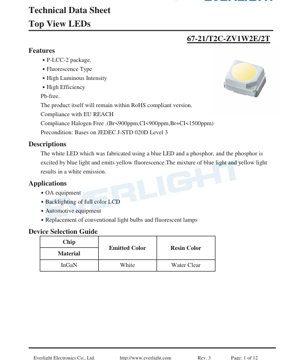
1. Product Overview
This document details the specifications for a high-performance white light-emitting diode (LED) utilizing a blue LED chip combined with a phosphor coating. The device is housed in a compact P-LCC-2 (Plastic Leaded Chip Carrier) surface-mount package, designed for top-view applications where light emission is perpendicular to the mounting plane. The core technology involves a blue LED exciting a yellow phosphor; the resultant mix of blue and yellow light produces a white emission. This approach is standard for producing white light from solid-state sources and offers advantages in efficiency and color tuning.
The LED is characterized by its high luminous intensity and efficiency. It is constructed using lead-free (Pb-free) materials and complies with major environmental regulations including RoHS, EU REACH, and halogen-free standards (Br<900ppm, Cl<900ppm, Br+Cl<1500ppm). The device is preconditioned according to the moisture sensitivity level 3 standard (JEDEC J-STD-020D), indicating its robustness for standard surface-mount assembly processes.
2. Technical Parameter Deep Dive
2.1 Absolute Maximum Ratings
The device must not be operated beyond these limits to prevent permanent damage. Key ratings include a maximum reverse voltage (VR) of 5V, a continuous forward current (IF) of 30mA, and a peak forward current (IFP) of 100mA under pulsed conditions (1/10 duty cycle at 1kHz). The maximum power dissipation (Pd) is 110mW. The operating temperature range is from -40°C to +85°C, with a slightly wider storage range of -40°C to +90°C. For soldering, it can withstand reflow profiles with a peak temperature of 260°C for 10 seconds or hand soldering at 350°C for 3 seconds. The electrostatic discharge (ESD) withstand voltage is 1000V (Human Body Model).
2.2 Electro-Optical Characteristics
Measured at a standard test condition of 25°C ambient temperature and a forward current of 20mA, the key performance parameters are defined. The luminous intensity (Iv) has a typical range from a minimum of 715 millicandelas (mcd) to a maximum of 2240 mcd, with a specified tolerance of ±11%. The viewing angle (2θ1/2), defined as the full angle at half intensity, is typically 120 degrees, providing a wide beam pattern. The forward voltage (VF) ranges from 2.75V to 3.65V at 20mA, with a tolerance of ±0.05V. The reverse current (IR) is specified at a maximum of 50µA when a reverse bias of 5V is applied.
3. Binning System Explanation
To ensure consistency in production, LEDs are sorted into bins based on key parameters. This allows designers to select parts that meet specific application requirements for brightness and electrical characteristics.
3.1 Luminous Intensity Binning
The luminous output is categorized into five distinct bins: V1 (715-900 mcd), V2 (900-1120 mcd), W1 (1120-1420 mcd), W2 (1420-1800 mcd), and BA (1800-2240 mcd). All measurements are taken at IF=20mA.
3.2 Forward Voltage Binning
The forward voltage is grouped into three bins under the general group "V": E5 (2.75-3.05V), 6 (3.05-3.35V), and 7 (3.35-3.65V). The tolerance for this binning is ±0.1V.
3.3 Chromaticity Coordinate Binning
The color of the white light is precisely controlled and binned according to its coordinates on the CIE 1931 chromaticity diagram. The bins are labeled (e.g., A0-1, A0-2, A0+1, A0+2, etc.) and define specific quadrilateral areas on the x,y color space. A tolerance of ±0.01 is applied to these coordinates. A diagram is typically provided to visualize these bins on the chromaticity chart, ensuring the emitted white light falls within a desired color temperature and tint range.
4. Performance Curve Analysis
Graphical data provides deeper insight into the LED's behavior under varying conditions.
- Forward Current vs. Forward Voltage (IV Curve): This curve shows the nonlinear relationship between current and voltage. It is essential for designing the current-limiting circuitry.
- Relative Luminous Intensity vs. Forward Current: This graph demonstrates how light output increases with current, typically in a sub-linear fashion at higher currents due to efficiency droop.
- Relative Luminous Intensity vs. Ambient Temperature: This critical curve shows the reduction in light output as the junction temperature rises. Understanding this derating is vital for thermal management in the application.
- Forward Current Derating Curve: This defines the maximum allowable forward current as a function of ambient temperature to stay within the power dissipation limits.
- Spectrum Distribution: A plot of relative intensity versus wavelength, showing the characteristic broad yellow phosphor emission peak combined with the narrower blue LED peak.
- Radiation Diagram: A polar plot illustrating the spatial distribution of light intensity, confirming the 120-degree viewing angle.
5. Mechanical and Packaging Information
5.1 Package Dimensions
The P-LCC-2 package has specific mechanical drawings detailing its length, width, height, lead dimensions, and recommended PCB land pattern. All dimensions are in millimeters with a standard tolerance of ±0.1mm unless otherwise noted. The package features two leads for electrical connection, with a clear polarity indicator (typically a notch or a marked cathode).
5.2 Polarity Identification
A label explanation diagram indicates how the product marking on the top of the LED corresponds to its performance bins: one code for Luminous Intensity Rank (CAT), one for Dominant Wavelength/Chromaticity Rank (HUE), and one for Forward Voltage Rank (REF).
6. Soldering and Assembly Guidelines
The device is suitable for standard SMT assembly lines. The maximum soldering temperature ratings must be strictly adhered to: 260°C peak temperature for 10 seconds during reflow soldering, or 350°C for 3 seconds if hand soldering. The moisture sensitivity level (MSL) is 3, meaning the components are packaged in a moisture-barrier bag with desiccant and have a floor life of 168 hours (1 week) after the bag is opened at factory conditions (<30°C/60%RH).
7. Packaging and Ordering Information
The LEDs are supplied on embossed carrier tapes for automated placement. Each reel contains 2000 pieces. Detailed dimensions for the carrier tape pockets and the overall reel are provided. The components are shipped in a sealed aluminum moisture-proof bag containing desiccant, with appropriate humidity indicator and warning labels affixed to the outside.
8. Application Suggestions
8.1 Typical Application Scenarios
This high-brightness white LED is suitable for a variety of applications requiring compact, efficient illumination. Primary uses include backlighting for full-color liquid crystal displays (LCDs) in consumer electronics and industrial panels, indicator lights and status illumination in office automation (OA) equipment, automotive interior lighting and indicators, and as a replacement for small conventional incandescent bulbs or fluorescent lamps in signage and decorative lighting.
8.2 Design Considerations
Current Drive: LEDs are current-driven devices. A constant current source or a current-limiting resistor in series with a voltage source is mandatory to prevent thermal runaway and ensure stable light output. The design must account for the forward voltage bin and its variation with temperature.
Thermal Management: Although efficient, LEDs generate heat at the junction. Excessive temperature reduces light output and lifespan. Ensure the PCB provides adequate thermal relief, especially when driving at or near the maximum current.
Optical Design: The 120-degree viewing angle provides a wide, diffuse beam. For focused light, secondary optics (lenses, reflectors) will be required. The water-clear resin color is optimal for applications where the LED chip itself should not be tinted.
9. Technical Comparison and Differentiation
Compared to earlier through-hole white LEDs, this SMT P-LCC-2 package offers significant advantages in board space savings, suitability for automated assembly, and potentially better thermal path to the PCB. The specified high luminous intensity bins (W2, BA) offer performance suitable for applications requiring high brightness in a small footprint. The comprehensive binning system for intensity, voltage, and chromaticity provides designers with the flexibility to select parts for cost-optimized or performance-critical designs, ensuring color and brightness consistency within an assembly.
10. Frequently Asked Questions (Based on Technical Parameters)
Q: What is the typical operating current for this LED?
A: The standard test condition and most data sheet specifications are given at 20mA. It can be operated up to its absolute maximum of 30mA continuous current, but light output and efficiency should be verified from the performance curves, and thermal management becomes more critical.
Q: How do I interpret the chromaticity bin codes (e.g., A0+2)?
A: These codes correspond to specific regions on the CIE color chart defined in the datasheet. They ensure the white point (correlated color temperature and tint) is within a controlled range. Designers should select bins that match their product's color consistency requirements.
Q: Can I drive this LED directly from a 5V supply?
A: Not without a current-limiting mechanism. The forward voltage is typically around 3.0-3.4V. Connecting 5V directly would cause excessive current, exceeding the maximum rating and destroying the LED. A series resistor or constant-current driver is necessary.
11. Practical Application Case
Scenario: Designing a status indicator panel for industrial equipment. Multiple white LEDs are used to illuminate translucent icons. To ensure uniform brightness, LEDs from the same luminous intensity bin (e.g., W1) should be selected. A simple drive circuit using a 12V rail and a series resistor for each LED can be designed. The resistor value is calculated as R = (V_supply - VF_LED) / I_LED. Using a typical VF of 3.2V from bin 6 and a desired current of 20mA, R = (12V - 3.2V) / 0.02A = 440 Ohms (a standard 470 Ohm resistor would result in ~18.7mA, which is acceptable). The wide 120-degree viewing angle ensures the icon is evenly lit without hotspots.
12. Operating Principle Introduction
This is a phosphor-converted white LED. The fundamental light source is a semiconductor chip made of Indium Gallium Nitride (InGaN) that emits blue light when forward biased (electroluminescence). This blue light is partially absorbed by a layer of cerium-doped yttrium aluminum garnet (YAG:Ce) phosphor coating applied over the chip. The phosphor absorbs the high-energy blue photons and re-emits lower-energy yellow light through a process called photoluminescence. The remaining unabsorbed blue light mixes with the emitted yellow light. The human eye perceives this combination of spectral components as white light. The exact shade or color temperature of the white light can be tuned by adjusting the phosphor composition and thickness.
13. Technology Trends
The development of white LEDs has been central to the solid-state lighting revolution. Ongoing trends focus on increasing luminous efficacy (lumens per watt), improving color rendering index (CRI) for more natural light, and achieving higher reliability and longer lifetimes. Advancements in phosphor technology, including the use of quantum dots or multi-phosphor blends, allow for finer control over the emission spectrum. There is also a drive towards miniaturization while maintaining or increasing light output, as seen in micro-LEDs. Furthermore, the integration of control electronics directly with the LED package for smart lighting applications is a growing area of development.
LED Specification Terminology
Complete explanation of LED technical terms
Photoelectric Performance
| Term | Unit/Representation | Simple Explanation | Why Important |
|---|---|---|---|
| Luminous Efficacy | lm/W (lumens per watt) | Light output per watt of electricity, higher means more energy efficient. | Directly determines energy efficiency grade and electricity cost. |
| Luminous Flux | lm (lumens) | Total light emitted by source, commonly called "brightness". | Determines if the light is bright enough. |
| Viewing Angle | ° (degrees), e.g., 120° | Angle where light intensity drops to half, determines beam width. | Affects illumination range and uniformity. |
| CCT (Color Temperature) | K (Kelvin), e.g., 2700K/6500K | Warmth/coolness of light, lower values yellowish/warm, higher whitish/cool. | Determines lighting atmosphere and suitable scenarios. |
| CRI / Ra | Unitless, 0–100 | Ability to render object colors accurately, Ra≥80 is good. | Affects color authenticity, used in high-demand places like malls, museums. |
| SDCM | MacAdam ellipse steps, e.g., "5-step" | Color consistency metric, smaller steps mean more consistent color. | Ensures uniform color across same batch of LEDs. |
| Dominant Wavelength | nm (nanometers), e.g., 620nm (red) | Wavelength corresponding to color of colored LEDs. | Determines hue of red, yellow, green monochrome LEDs. |
| Spectral Distribution | Wavelength vs intensity curve | Shows intensity distribution across wavelengths. | Affects color rendering and quality. |
Electrical Parameters
| Term | Symbol | Simple Explanation | Design Considerations |
|---|---|---|---|
| Forward Voltage | Vf | Minimum voltage to turn on LED, like "starting threshold". | Driver voltage must be ≥Vf, voltages add up for series LEDs. |
| Forward Current | If | Current value for normal LED operation. | Usually constant current drive, current determines brightness & lifespan. |
| Max Pulse Current | Ifp | Peak current tolerable for short periods, used for dimming or flashing. | Pulse width & duty cycle must be strictly controlled to avoid damage. |
| Reverse Voltage | Vr | Max reverse voltage LED can withstand, beyond may cause breakdown. | Circuit must prevent reverse connection or voltage spikes. |
| Thermal Resistance | Rth (°C/W) | Resistance to heat transfer from chip to solder, lower is better. | High thermal resistance requires stronger heat dissipation. |
| ESD Immunity | V (HBM), e.g., 1000V | Ability to withstand electrostatic discharge, higher means less vulnerable. | Anti-static measures needed in production, especially for sensitive LEDs. |
Thermal Management & Reliability
| Term | Key Metric | Simple Explanation | Impact |
|---|---|---|---|
| Junction Temperature | Tj (°C) | Actual operating temperature inside LED chip. | Every 10°C reduction may double lifespan; too high causes light decay, color shift. |
| Lumen Depreciation | L70 / L80 (hours) | Time for brightness to drop to 70% or 80% of initial. | Directly defines LED "service life". |
| Lumen Maintenance | % (e.g., 70%) | Percentage of brightness retained after time. | Indicates brightness retention over long-term use. |
| Color Shift | Δu′v′ or MacAdam ellipse | Degree of color change during use. | Affects color consistency in lighting scenes. |
| Thermal Aging | Material degradation | Deterioration due to long-term high temperature. | May cause brightness drop, color change, or open-circuit failure. |
Packaging & Materials
| Term | Common Types | Simple Explanation | Features & Applications |
|---|---|---|---|
| Package Type | EMC, PPA, Ceramic | Housing material protecting chip, providing optical/thermal interface. | EMC: good heat resistance, low cost; Ceramic: better heat dissipation, longer life. |
| Chip Structure | Front, Flip Chip | Chip electrode arrangement. | Flip chip: better heat dissipation, higher efficacy, for high-power. |
| Phosphor Coating | YAG, Silicate, Nitride | Covers blue chip, converts some to yellow/red, mixes to white. | Different phosphors affect efficacy, CCT, and CRI. |
| Lens/Optics | Flat, Microlens, TIR | Optical structure on surface controlling light distribution. | Determines viewing angle and light distribution curve. |
Quality Control & Binning
| Term | Binning Content | Simple Explanation | Purpose |
|---|---|---|---|
| Luminous Flux Bin | Code e.g., 2G, 2H | Grouped by brightness, each group has min/max lumen values. | Ensures uniform brightness in same batch. |
| Voltage Bin | Code e.g., 6W, 6X | Grouped by forward voltage range. | Facilitates driver matching, improves system efficiency. |
| Color Bin | 5-step MacAdam ellipse | Grouped by color coordinates, ensuring tight range. | Guarantees color consistency, avoids uneven color within fixture. |
| CCT Bin | 2700K, 3000K etc. | Grouped by CCT, each has corresponding coordinate range. | Meets different scene CCT requirements. |
Testing & Certification
| Term | Standard/Test | Simple Explanation | Significance |
|---|---|---|---|
| LM-80 | Lumen maintenance test | Long-term lighting at constant temperature, recording brightness decay. | Used to estimate LED life (with TM-21). |
| TM-21 | Life estimation standard | Estimates life under actual conditions based on LM-80 data. | Provides scientific life prediction. |
| IESNA | Illuminating Engineering Society | Covers optical, electrical, thermal test methods. | Industry-recognized test basis. |
| RoHS / REACH | Environmental certification | Ensures no harmful substances (lead, mercury). | Market access requirement internationally. |
| ENERGY STAR / DLC | Energy efficiency certification | Energy efficiency and performance certification for lighting. | Used in government procurement, subsidy programs, enhances competitiveness. |