1. Product Overview
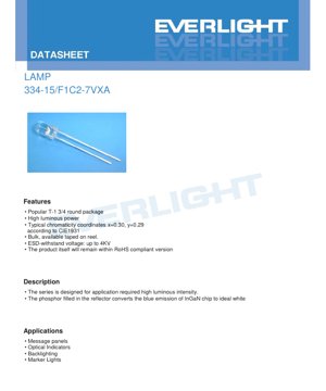
This document details the specifications for a high-luminosity white LED lamp. The device is housed in a popular T-1 3/4 round package, making it suitable for a wide range of indicator and illumination applications. Its core advantage lies in the combination of a compact, industry-standard form factor with high luminous output.
The primary target markets include applications requiring clear, bright visual indicators, such as message panels, status indicators, backlighting for small displays, and marker lights. The product is designed to meet general requirements for reliability and performance in consumer and industrial electronics.
2. Technical Parameter Deep-Dive
2.1 Absolute Maximum Ratings
The device is designed to operate within strict electrical and thermal limits to ensure long-term reliability. The continuous forward current (IF) is rated at 30 mA, with a peak forward current (IFP) of 100 mA permissible under pulsed conditions (duty cycle 1/10 at 1 kHz). The maximum reverse voltage (VR) is 5 V. The total power dissipation (Pd) must not exceed 110 mW. The operating temperature range is from -40°C to +85°C, and storage can be from -40°C to +100°C. The device can withstand electrostatic discharge (ESD) up to 4 kV (Human Body Model). The maximum soldering temperature is 260°C for 5 seconds.
2.2 Electro-Optical Characteristics
Key performance parameters are measured at a standard test condition of 20 mA forward current and an ambient temperature (Ta) of 25°C. The forward voltage (VF) typically falls between 2.8 V and 3.6 V. The luminous intensity (IV) has a typical value, with a wide binning range from 11,250 mcd to 22,500 mcd. The viewing angle (2θ1/2) is approximately 20 degrees, providing a relatively focused beam. The typical chromaticity coordinates are x=0.30, y=0.29 according to the CIE 1931 color space, indicating a white point. The reverse current (IR) is limited to a maximum of 50 μA at 5 V reverse bias.
3. Binning System Explanation
3.1 Luminous Intensity Binning
The LEDs are sorted into bins based on their measured luminous intensity at 20 mA. This ensures consistency in brightness for production applications. The bin codes are V (11,250-14,250 mcd), W (14,250-18,000 mcd), and X (18,000-22,500 mcd). A general tolerance of ±10% applies to the luminous intensity.
3.2 Forward Voltage Binning
To aid in circuit design for voltage drop and current regulation, LEDs are also binned by forward voltage. The bins are 0 (2.8-3.0V), 1 (3.0-3.2V), 2 (3.2-3.4V), and 3 (3.4-3.6V). The measurement uncertainty for this parameter is ±0.1V.
3.3 Color Binning
The white color point is controlled within specific regions on the CIE chromaticity diagram. The product uses a combination of color groups, specifically B5 and B6. The coordinates for these groups define a quadrilateral area on the CIE chart, ensuring the white light output falls within an acceptable correlated color temperature (CCT) range, visually indicated between 5600K and 9000K on the provided diagram.
4. Performance Curve Analysis
The datasheet includes several characteristic curves that are crucial for design engineers. The Relative Intensity vs. Wavelength curve shows the spectral power distribution of the white light, which is a broad spectrum resulting from a blue InGaN chip exciting a phosphor. The Directivity pattern illustrates the spatial distribution of light, confirming the 20-degree viewing angle. The Forward Current vs. Forward Voltage (I-V Curve) is essential for determining the operating point and designing the current-limiting circuitry. The Relative Intensity vs. Forward Current curve shows how light output scales with drive current, important for dimming or over-driving considerations. The Chromaticity Coordinate vs. Forward Current graph indicates how the white point may shift with different drive currents. Finally, the Forward Current vs. Ambient Temperature curve is critical for understanding derating requirements and thermal management needs in the application.
5. Mechanical and Package Information
The LED uses a standard T-1 3/4 (5mm) round package with two axial leads. A detailed dimensioned drawing is provided. Key dimensions include the lead diameter, the bulb diameter, and the overall length. The lead spacing is measured where the leads exit the package body. Notes specify that all dimensions are in millimeters with a standard tolerance of ±0.25mm unless otherwise stated. The maximum protrusion of resin under the flange is 1.5mm. Proper alignment of PCB holes with the LED leads is emphasized to avoid mechanical stress during mounting.
6. Soldering and Assembly Guidelines
Proper handling is required to maintain device integrity. For lead forming, bending must occur at least 3mm from the base of the epoxy bulb and should be done before soldering. Stress on the package must be avoided. Cutting leads should be done at room temperature. For storage, LEDs should be kept at ≤30°C and ≤70% RH. The shelf life from shipment is 3 months; for longer storage, a nitrogen-filled, moisture-controlled environment is recommended. Rapid temperature changes in humid conditions should be avoided. For soldering, the joint must be at least 3mm from the epoxy bulb. Recommended conditions are: for hand soldering, an iron tip temperature ≤300°C (30W max) for ≤3 seconds; for wave or dip soldering, a preheat ≤100°C for ≤60 seconds and a solder bath at ≤260°C for ≤5 seconds.
7. Packaging and Ordering Information
The LEDs are packaged in moisture-resistant, anti-static materials. They are supplied in anti-electrostatic bags, placed in inner cartons, which are then packed into outside cartons. The packing quantity is flexible: a minimum of 200 to a maximum of 500 pieces per bag, with 5 bags per inner carton, and 10 inner cartons per master (outside) carton. The label on the packaging includes fields for Customer's Production Number (CPN), Part Number (P/N), Quantity (QTY), Luminous Intensity and Voltage Rank (CAT), Color Rank (HUE), Reference (REF), Lot Number (LOT No.), and Production Place.
8. Application Suggestions
8.1 Typical Application Scenarios
This high-intensity LED is ideal for applications requiring a bright, point-source light. Primary uses include: Message Panels and Signage: Where individual pixels need to be clearly visible. Optical Status Indicators: In equipment where a bright "power on" or "system active" signal is needed, even in well-lit environments. Backlighting: For small LCD displays, keypads, or panel legends. Marker and Position Lights: In consumer electronics, automotive interiors, or industrial controls.
8.2 Design Considerations
When designing with this LED, engineers must consider: Current Limiting: Always use a series resistor or constant current driver to maintain the forward current at or below 30 mA continuous. The I-V curve should be referenced for the specific VF bin. Thermal Management: Although power dissipation is low, ensuring the device operates within its temperature rating is vital for longevity, especially in enclosed spaces or high ambient temperatures. Refer to the derating curve. Viewing Angle: The 20-degree beam is relatively narrow. For wider illumination, diffusers or lenses may be required. ESD Protection: While rated for 4kV HBM, standard ESD precautions during handling and assembly are recommended.
9. Technical Comparison and Differentiation
Compared to generic 5mm white LEDs, this product differentiates itself primarily through its high luminous intensity binning, offering guaranteed minimum outputs up to 22,500 mcd, which is significantly brighter than standard offerings. The provision of detailed forward voltage and color binning allows for tighter design control in applications where color consistency or precise voltage drop is critical, such as in multi-LED arrays or battery-powered devices. The inclusion of a Zener diode (with specified VZ and IZ) for reverse voltage protection is a feature not found in all basic LEDs, adding a layer of robustness in circuit designs susceptible to voltage transients.
10. Frequently Asked Questions (Based on Technical Parameters)
Q: What resistor value should I use for a 12V supply?
A: Using Ohm's Law (R = (Vsupply - VF) / IF) and assuming a typical VF of 3.2V and desired IF of 20mA: R = (12V - 3.2V) / 0.02A = 440 Ω. Use the next standard value (e.g., 470 Ω) and check the actual current and power rating of the resistor.
Q: Can I drive this LED at 30mA continuously?
A: Yes, 30mA is the rated continuous forward current. However, operating at the maximum rating may reduce lifetime and increase junction temperature. For optimal longevity, driving at 20mA or lower is recommended if the luminous intensity is sufficient.
Q: How does temperature affect performance?
A: As shown in the Forward Current vs. Ambient Temperature curve, the allowable forward current decreases as ambient temperature rises above 25°C to keep the junction temperature within safe limits. Luminous output also typically decreases with increasing junction temperature.
Q: What is the purpose of the color bins B5 and B6?
A: These bins define a specific region on the CIE color chart. Mixing LEDs from these bins allows for a consistent white color appearance in an assembly, even if individual units have slight variations. It ensures the white point remains within a visually acceptable range, typically appearing cool white.
11. Practical Design and Usage Case
Case: Designing a High-Visibility Status Indicator for Outdoor Equipment
An engineer needs a status LED visible in direct sunlight. Selecting an LED from the highest luminous bin (X: 18,000-22,500 mcd) is crucial. To ensure reliability in an outdoor environment with temperature extremes, thermal analysis is performed using the derating curve. The LED will be driven at 20mA using a constant-current circuit to maintain brightness regardless of small battery voltage fluctuations. The narrow 20-degree viewing angle is an advantage here, concentrating the light toward the user's expected line of sight. A conformal coating might be applied to the PCB, but care must be taken not to contaminate the LED lens, and the coating must be compatible with the epoxy resin.
12. Operating Principle Introduction
This is a phosphor-converted white LED. The core light-emitting element is a semiconductor chip made of Indium Gallium Nitride (InGaN). When forward current is applied, electrons and holes recombine within the chip, emitting photons primarily in the blue region of the spectrum. This blue light is not emitted directly. Instead, it strikes a layer of phosphor material (typically Yttrium Aluminum Garnet doped with Cerium, or YAG:Ce) that is deposited inside the LED package's reflector cup. The phosphor absorbs a portion of the blue light and re-emits it as a broad spectrum of yellow light. The combination of the remaining blue light and the generated yellow light mixes to produce the perception of white light to the human eye. The exact shade or correlated color temperature (CCT) of the white light is determined by the composition and thickness of the phosphor layer.
13. Technology Trends and Context
The T-1 3/4 (5mm) round LED package is a mature and widely adopted technology. Its key advantages are low cost, ease of handling for through-hole assembly, and high reliability. The trend in the broader LED industry is towards surface-mount device (SMD) packages (like 2835, 5050, etc.) for higher density, better thermal management, and automated assembly. However, the through-hole package remains relevant for applications requiring high single-point luminosity, robustness in high-vibration environments, manual assembly, or repair, and in educational or hobbyist contexts. The technology described here represents the optimization of a classic package type, focusing on delivering high luminous intensity and well-defined performance parameters to meet the needs of both legacy and specific modern applications where its form factor and performance characteristics are ideal.
LED Specification Terminology
Complete explanation of LED technical terms
Photoelectric Performance
| Term | Unit/Representation | Simple Explanation | Why Important |
|---|---|---|---|
| Luminous Efficacy | lm/W (lumens per watt) | Light output per watt of electricity, higher means more energy efficient. | Directly determines energy efficiency grade and electricity cost. |
| Luminous Flux | lm (lumens) | Total light emitted by source, commonly called "brightness". | Determines if the light is bright enough. |
| Viewing Angle | ° (degrees), e.g., 120° | Angle where light intensity drops to half, determines beam width. | Affects illumination range and uniformity. |
| CCT (Color Temperature) | K (Kelvin), e.g., 2700K/6500K | Warmth/coolness of light, lower values yellowish/warm, higher whitish/cool. | Determines lighting atmosphere and suitable scenarios. |
| CRI / Ra | Unitless, 0–100 | Ability to render object colors accurately, Ra≥80 is good. | Affects color authenticity, used in high-demand places like malls, museums. |
| SDCM | MacAdam ellipse steps, e.g., "5-step" | Color consistency metric, smaller steps mean more consistent color. | Ensures uniform color across same batch of LEDs. |
| Dominant Wavelength | nm (nanometers), e.g., 620nm (red) | Wavelength corresponding to color of colored LEDs. | Determines hue of red, yellow, green monochrome LEDs. |
| Spectral Distribution | Wavelength vs intensity curve | Shows intensity distribution across wavelengths. | Affects color rendering and quality. |
Electrical Parameters
| Term | Symbol | Simple Explanation | Design Considerations |
|---|---|---|---|
| Forward Voltage | Vf | Minimum voltage to turn on LED, like "starting threshold". | Driver voltage must be ≥Vf, voltages add up for series LEDs. |
| Forward Current | If | Current value for normal LED operation. | Usually constant current drive, current determines brightness & lifespan. |
| Max Pulse Current | Ifp | Peak current tolerable for short periods, used for dimming or flashing. | Pulse width & duty cycle must be strictly controlled to avoid damage. |
| Reverse Voltage | Vr | Max reverse voltage LED can withstand, beyond may cause breakdown. | Circuit must prevent reverse connection or voltage spikes. |
| Thermal Resistance | Rth (°C/W) | Resistance to heat transfer from chip to solder, lower is better. | High thermal resistance requires stronger heat dissipation. |
| ESD Immunity | V (HBM), e.g., 1000V | Ability to withstand electrostatic discharge, higher means less vulnerable. | Anti-static measures needed in production, especially for sensitive LEDs. |
Thermal Management & Reliability
| Term | Key Metric | Simple Explanation | Impact |
|---|---|---|---|
| Junction Temperature | Tj (°C) | Actual operating temperature inside LED chip. | Every 10°C reduction may double lifespan; too high causes light decay, color shift. |
| Lumen Depreciation | L70 / L80 (hours) | Time for brightness to drop to 70% or 80% of initial. | Directly defines LED "service life". |
| Lumen Maintenance | % (e.g., 70%) | Percentage of brightness retained after time. | Indicates brightness retention over long-term use. |
| Color Shift | Δu′v′ or MacAdam ellipse | Degree of color change during use. | Affects color consistency in lighting scenes. |
| Thermal Aging | Material degradation | Deterioration due to long-term high temperature. | May cause brightness drop, color change, or open-circuit failure. |
Packaging & Materials
| Term | Common Types | Simple Explanation | Features & Applications |
|---|---|---|---|
| Package Type | EMC, PPA, Ceramic | Housing material protecting chip, providing optical/thermal interface. | EMC: good heat resistance, low cost; Ceramic: better heat dissipation, longer life. |
| Chip Structure | Front, Flip Chip | Chip electrode arrangement. | Flip chip: better heat dissipation, higher efficacy, for high-power. |
| Phosphor Coating | YAG, Silicate, Nitride | Covers blue chip, converts some to yellow/red, mixes to white. | Different phosphors affect efficacy, CCT, and CRI. |
| Lens/Optics | Flat, Microlens, TIR | Optical structure on surface controlling light distribution. | Determines viewing angle and light distribution curve. |
Quality Control & Binning
| Term | Binning Content | Simple Explanation | Purpose |
|---|---|---|---|
| Luminous Flux Bin | Code e.g., 2G, 2H | Grouped by brightness, each group has min/max lumen values. | Ensures uniform brightness in same batch. |
| Voltage Bin | Code e.g., 6W, 6X | Grouped by forward voltage range. | Facilitates driver matching, improves system efficiency. |
| Color Bin | 5-step MacAdam ellipse | Grouped by color coordinates, ensuring tight range. | Guarantees color consistency, avoids uneven color within fixture. |
| CCT Bin | 2700K, 3000K etc. | Grouped by CCT, each has corresponding coordinate range. | Meets different scene CCT requirements. |
Testing & Certification
| Term | Standard/Test | Simple Explanation | Significance |
|---|---|---|---|
| LM-80 | Lumen maintenance test | Long-term lighting at constant temperature, recording brightness decay. | Used to estimate LED life (with TM-21). |
| TM-21 | Life estimation standard | Estimates life under actual conditions based on LM-80 data. | Provides scientific life prediction. |
| IESNA | Illuminating Engineering Society | Covers optical, electrical, thermal test methods. | Industry-recognized test basis. |
| RoHS / REACH | Environmental certification | Ensures no harmful substances (lead, mercury). | Market access requirement internationally. |
| ENERGY STAR / DLC | Energy efficiency certification | Energy efficiency and performance certification for lighting. | Used in government procurement, subsidy programs, enhances competitiveness. |