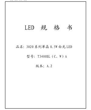
1. Product Overview
The 3020 series is a high-performance, single-chip, surface-mount LED designed for general lighting applications requiring reliable performance and consistent color output. This 0.5W white LED offers a balance of efficiency, lumen output, and thermal management in a compact 3.0mm x 2.0mm footprint.
Core Advantages: The primary advantages of this series include its standardized binning system for color temperature and luminous flux, ensuring color consistency in production runs. It features a wide viewing angle of 110 degrees, making it suitable for applications requiring broad illumination. The product is designed to meet industry standards for moisture sensitivity and reflow soldering.
Target Market: This LED is targeted at manufacturers of LED modules, light panels, backlighting units, decorative lighting, and other applications where a compact, efficient, and consistent white light source is required.
2. Technical Parameter Deep Dive
2.1 Absolute Maximum Ratings
The following parameters define the limits beyond which permanent damage to the LED may occur. Operation under these conditions is not guaranteed.
- Forward Current (IF): 200 mA (Continuous)
- Forward Pulse Current (IFP): 300 mA (Pulse width ≤10ms, Duty cycle ≤1/10)
- Power Dissipation (PD): 680 mW
- Operating Temperature (Topr): -40°C to +80°C
- Storage Temperature (Tstg): -40°C to +80°C
- Junction Temperature (Tj): 125°C
- Soldering Temperature (Tsld): Reflow soldering at 230°C or 260°C for a maximum of 10 seconds.
2.2 Typical Electrical & Optical Characteristics
Measured at a standard test condition of a 25°C solder point temperature (Ts).
- Forward Voltage (VF): Typical 3.2V, Maximum 3.5V (at IF=150mA)
- Reverse Voltage (VR): 5V
- Reverse Current (IR): Maximum 10 µA
- Viewing Angle (2θ1/2): 110°
3. Binning System Explanation
The product employs a comprehensive binning system to ensure electrical and optical consistency. Orders specify minimum values for luminous flux and defined chromaticity regions for color temperature.
3.1 Color Temperature (CCT) Binning
The LED is available in several standard Correlated Color Temperature (CCT) bins, each defined by a target CCT and a specific chromaticity ellipse on the CIE diagram.
- 2725K ±145K (Bin: 27M5)
- 3045K ±175K (Bin: 30M5)
- 3985K ±275K (Bin: 40M5)
- 5028K ±283K (Bin: 50M5)
- 5665K ±355K (Bin: 57M7)
- 6530K ±510K (Bin: 65M7)
Note: The product ordering specifies the chromaticity region, not a maximum CCT value. Shipped products will always fall within the ordered chromaticity ellipse.
3.2 Luminous Flux Binning
Flux is binned based on Color Temperature and Color Rendering Index (CRI). The tables define minimum and typical values at 150mA. The standard flux codes (E5, E6, E7, etc.) represent a range in lumens.
Example for 70 CRI, Neutral White (3700-5000K):
- Code E6: 50-54 lm (Min-Typ)
- Code E7: 54-58 lm
- Code E8: 58-62 lm
- Code E9: 62-66 lm
Similar tables exist for Warm White, Cool White, and their respective high-CRI (80 CRI) versions.
3.3 Forward Voltage Binning
Forward voltage is also binned to ensure consistent string voltage in series configurations.
- Code B: 2.8 - 2.9V
- Code C: 2.9 - 3.0V
- Code D: 3.0 - 3.1V
- Code E: 3.1 - 3.2V
- Code F: 3.2 - 3.3V
- Code G: 3.3 - 3.4V
- Code H: 3.4 - 3.5V
3.4 Chromaticity Ellipse Data
Each color temperature bin corresponds to a specific ellipse on the CIE 1931 chromaticity diagram, defined by its center coordinates (x, y), semi-major axis (b), semi-minor axis (a), and tilt angle (Φ). This data is crucial for precise color mixing and quality control.
4. Performance Curve Analysis
4.1 IV Characteristic Curve
The Forward Current vs. Forward Voltage (IV) curve shows the typical exponential relationship. At the recommended operating current of 150mA, the forward voltage typically sits around 3.2V. Designers must use current-limiting drivers, not voltage sources, to ensure stable operation.
4.2 Relative Luminous Flux vs. Forward Current
This curve illustrates the relationship between drive current and light output. Luminous flux increases with current but exhibits a sub-linear trend at higher currents due to increased junction temperature and efficiency droop. Operating significantly above 150mA is not recommended for optimal lifetime and efficiency.
4.3 Spectral Power Distribution (SPD)
The relative spectral energy curve shows the emission spectrum for different CCT ranges (e.g., 2600-3700K, 3700-5000K, 5000-10000K). Warmer CCTs have more energy in the red/yellow region, while cooler CCTs have a bluer peak. The curve is essential for calculating color rendering metrics.
4.4 Junction Temperature vs. Relative Spectral Energy
This graph depicts how the spectral output shifts with increasing junction temperature (Tj). Typically, as Tj rises, the peak wavelength may shift slightly, and the overall intensity can decrease. This underscores the importance of effective thermal management in the application design to maintain consistent color and light output.
5. Mechanical & Package Information
5.1 Package Dimensions
The LED has a standard 3020 (3.0mm x 2.0mm) SMD footprint. Detailed dimensional drawings specify the package body, lens, and lead dimensions with associated tolerances (e.g., ±0.10mm for .X dimensions, ±0.05mm for .XX dimensions).
5.2 Pad Pattern & Stencil Design
Separate drawings are provided for the recommended PCB land pattern (pad layout) and the solder paste stencil design. Adhering to these recommendations is critical for achieving proper solder joint formation, alignment, and thermal transfer during reflow soldering.
5.3 Polarity Identification
The cathode (negative) terminal is typically marked on the LED package, often with a green marking or a notch in the lens. The PCB silkscreen and footprint should clearly indicate polarity to prevent reverse mounting.
6. Soldering & Assembly Guidelines
6.1 Moisture Sensitivity & Baking
The 3020 series LED is classified as moisture-sensitive according to IPC/JEDEC J-STD-020C. Exposure to ambient humidity after opening the moisture barrier bag can cause popcorn cracking or other damage during reflow.
Storage: Store unopened bags below 30°C/85% RH. After opening, store below 30°C/60% RH.
Baking Requirements: LEDs that have been removed from their original sealed packaging and exposed to ambient conditions must be baked before reflow.
Baking Method: Bake at 60°C for 24 hours on the original reel. Do not exceed 60°C. Use within 1 hour of baking or store in a dry cabinet (<20% RH).
6.2 Reflow Soldering Profile
A standard lead-free reflow profile is applicable. The maximum peak temperature at the LED solder joints should not exceed 260°C, and the time above 230°C should be limited to 10 seconds. Consult the detailed profile recommendations for preheat, soak, reflow, and cooling rates.
7. Packaging & Ordering Information
7.1 Packaging Specification
The LEDs are typically supplied on embossed carrier tapes wound onto reels, suitable for automated pick-and-place assembly. Standard reel quantities are specified (e.g., 2000 or 4000 pieces per reel). The reel is packaged inside a moisture barrier bag with a humidity indicator card.
7.2 Model Numbering Rule
The part number is structured to encode key attributes: Series/Shape (e.g., 34 for 3020), Chip Count (S for single), Lens Code (00 for none, 01 for with lens), Color Code (L/C/W for white temperatures), Internal Code, Luminous Flux Code (e.g., E6), and Forward Voltage Code (e.g., D). An example is T3400SLA-E6D.
8. Application Suggestions
8.1 Typical Application Scenarios
- LED Modules and Light Engines: For panel lights, downlights, and troffers.
- Backlighting: Edge-lit or direct-lit signage and displays.
- Decorative Lighting: Strips, ropes, and accent lighting.
- Consumer Electronics: Indicator or status lighting.
8.2 Design Considerations
- Thermal Management: Use a PCB with adequate thermal vias and, if necessary, a metal core (MCPCB) to dissipate heat and keep the junction temperature low for maximum lifetime and stable output.
- Current Drive: Always use a constant current driver. The recommended operating current is 150mA. Derating may be necessary in high ambient temperature environments.
- Optics: The 110-degree viewing angle is suitable for diffuse lighting. Secondary optics (lenses, reflectors) can be used to modify the beam pattern.
- ESD Protection: Implement standard ESD handling procedures during assembly, as LEDs are sensitive to electrostatic discharge.
9. Technical Comparison & Differentiation
Compared to older 3528 packages, the 3020 series often offers a higher power density (0.5W vs. 0.2W typical) in a slightly smaller footprint, enabling more compact designs. The standardized, detailed binning system for both flux and voltage provides a significant advantage for applications requiring tight color and brightness matching over large production volumes, reducing the need for post-production sorting or calibration by the end-user.
10. Frequently Asked Questions (FAQ)
10.1 What is the difference between ordering by minimum flux vs. typical flux?
The specification defines bins by a minimum luminous flux value. This means all shipped LEDs will meet or exceed that minimum value. The \"typical\" value is provided for reference, but the actual flux may be higher. This system guarantees performance while allowing for normal manufacturing variation above the minimum.
10.2 Why is baking necessary, and can I skip it if I use the LEDs quickly?
Baking is a critical process to remove absorbed moisture from the plastic package. Even short exposure to humid air can be sufficient to cause damage during the high-temperature reflow soldering process. It is not safe to skip baking based on time alone; the condition of the humidity indicator card inside the original bag must be checked to determine if baking is required.
10.3 Can I drive this LED at 200mA continuously?
While 200mA is the absolute maximum continuous current rating, operating at this level will generate significant heat, reduce efficiency (lumen per watt), and potentially shorten the LED's lifetime. The recommended operating condition is 150mA for optimal performance and reliability. Operation at 200mA requires exceptional thermal management.
11. Design and Usage Case Study
11.1 Designing a 12V LED Module
Scenario: Creating a compact 12V input LED module with 6 LEDs in series.
Design Steps:
- Electrical Design: Select LEDs from the same voltage bin (e.g., Bin D: 3.0-3.1V). The total forward voltage for 6 LEDs will be approximately 18.0V to 18.6V, which is higher than the 12V supply. Therefore, a step-up (boost) constant current driver is required, not a simple resistor.
- Thermal Design: Mount the LEDs on an aluminum-core PCB (MCPCB). Calculate the total power dissipation (~0.5W per LED * 6 = 3W) and ensure the heatsinking is sufficient to keep the LED solder point temperature within the specified operating range, ideally below 60°C for long life.
- Optical Consistency: Order all LEDs from the same luminous flux bin (e.g., E7) and color temperature bin (e.g., 40M5 for 4000K) to ensure uniform brightness and color across the module.
- Assembly: Follow the moisture handling and reflow soldering guidelines precisely to prevent yield loss.
12. Technical Principles
The LED operates on the principle of electroluminescence in a semiconductor chip, typically based on InGaN for white LEDs. A blue-emitting chip is coated with a phosphor layer. Part of the blue light is converted by the phosphor into longer wavelengths (yellow, red). The combination of the remaining blue light and the phosphor-converted light results in the perception of white light. The ratio of blue to yellow/red light determines the Correlated Color Temperature (CCT). The Color Rendering Index (CRI) is improved by using multiple phosphors to fill gaps in the spectrum. The forward voltage is a characteristic of the semiconductor material's bandgap and the chip construction.
13. Industry Trends
The general trend in mid-power SMD LEDs like the 3020 series is towards higher efficacy (more lumens per watt), improved color consistency (tighter binning), and higher reliability at elevated operating temperatures. There is also a drive for higher CRI values (90+) for applications requiring excellent color fidelity, such as retail and museum lighting. Furthermore, the industry continues to refine moisture-resistant packaging materials and processes to simplify handling and improve robustness for a wider range of assembly environments. The development of new phosphor systems aims to provide better spectral quality and stability over the LED's lifetime.
LED Specification Terminology
Complete explanation of LED technical terms
Photoelectric Performance
| Term | Unit/Representation | Simple Explanation | Why Important |
|---|---|---|---|
| Luminous Efficacy | lm/W (lumens per watt) | Light output per watt of electricity, higher means more energy efficient. | Directly determines energy efficiency grade and electricity cost. |
| Luminous Flux | lm (lumens) | Total light emitted by source, commonly called "brightness". | Determines if the light is bright enough. |
| Viewing Angle | ° (degrees), e.g., 120° | Angle where light intensity drops to half, determines beam width. | Affects illumination range and uniformity. |
| CCT (Color Temperature) | K (Kelvin), e.g., 2700K/6500K | Warmth/coolness of light, lower values yellowish/warm, higher whitish/cool. | Determines lighting atmosphere and suitable scenarios. |
| CRI / Ra | Unitless, 0–100 | Ability to render object colors accurately, Ra≥80 is good. | Affects color authenticity, used in high-demand places like malls, museums. |
| SDCM | MacAdam ellipse steps, e.g., "5-step" | Color consistency metric, smaller steps mean more consistent color. | Ensures uniform color across same batch of LEDs. |
| Dominant Wavelength | nm (nanometers), e.g., 620nm (red) | Wavelength corresponding to color of colored LEDs. | Determines hue of red, yellow, green monochrome LEDs. |
| Spectral Distribution | Wavelength vs intensity curve | Shows intensity distribution across wavelengths. | Affects color rendering and quality. |
Electrical Parameters
| Term | Symbol | Simple Explanation | Design Considerations |
|---|---|---|---|
| Forward Voltage | Vf | Minimum voltage to turn on LED, like "starting threshold". | Driver voltage must be ≥Vf, voltages add up for series LEDs. |
| Forward Current | If | Current value for normal LED operation. | Usually constant current drive, current determines brightness & lifespan. |
| Max Pulse Current | Ifp | Peak current tolerable for short periods, used for dimming or flashing. | Pulse width & duty cycle must be strictly controlled to avoid damage. |
| Reverse Voltage | Vr | Max reverse voltage LED can withstand, beyond may cause breakdown. | Circuit must prevent reverse connection or voltage spikes. |
| Thermal Resistance | Rth (°C/W) | Resistance to heat transfer from chip to solder, lower is better. | High thermal resistance requires stronger heat dissipation. |
| ESD Immunity | V (HBM), e.g., 1000V | Ability to withstand electrostatic discharge, higher means less vulnerable. | Anti-static measures needed in production, especially for sensitive LEDs. |
Thermal Management & Reliability
| Term | Key Metric | Simple Explanation | Impact |
|---|---|---|---|
| Junction Temperature | Tj (°C) | Actual operating temperature inside LED chip. | Every 10°C reduction may double lifespan; too high causes light decay, color shift. |
| Lumen Depreciation | L70 / L80 (hours) | Time for brightness to drop to 70% or 80% of initial. | Directly defines LED "service life". |
| Lumen Maintenance | % (e.g., 70%) | Percentage of brightness retained after time. | Indicates brightness retention over long-term use. |
| Color Shift | Δu′v′ or MacAdam ellipse | Degree of color change during use. | Affects color consistency in lighting scenes. |
| Thermal Aging | Material degradation | Deterioration due to long-term high temperature. | May cause brightness drop, color change, or open-circuit failure. |
Packaging & Materials
| Term | Common Types | Simple Explanation | Features & Applications |
|---|---|---|---|
| Package Type | EMC, PPA, Ceramic | Housing material protecting chip, providing optical/thermal interface. | EMC: good heat resistance, low cost; Ceramic: better heat dissipation, longer life. |
| Chip Structure | Front, Flip Chip | Chip electrode arrangement. | Flip chip: better heat dissipation, higher efficacy, for high-power. |
| Phosphor Coating | YAG, Silicate, Nitride | Covers blue chip, converts some to yellow/red, mixes to white. | Different phosphors affect efficacy, CCT, and CRI. |
| Lens/Optics | Flat, Microlens, TIR | Optical structure on surface controlling light distribution. | Determines viewing angle and light distribution curve. |
Quality Control & Binning
| Term | Binning Content | Simple Explanation | Purpose |
|---|---|---|---|
| Luminous Flux Bin | Code e.g., 2G, 2H | Grouped by brightness, each group has min/max lumen values. | Ensures uniform brightness in same batch. |
| Voltage Bin | Code e.g., 6W, 6X | Grouped by forward voltage range. | Facilitates driver matching, improves system efficiency. |
| Color Bin | 5-step MacAdam ellipse | Grouped by color coordinates, ensuring tight range. | Guarantees color consistency, avoids uneven color within fixture. |
| CCT Bin | 2700K, 3000K etc. | Grouped by CCT, each has corresponding coordinate range. | Meets different scene CCT requirements. |
Testing & Certification
| Term | Standard/Test | Simple Explanation | Significance |
|---|---|---|---|
| LM-80 | Lumen maintenance test | Long-term lighting at constant temperature, recording brightness decay. | Used to estimate LED life (with TM-21). |
| TM-21 | Life estimation standard | Estimates life under actual conditions based on LM-80 data. | Provides scientific life prediction. |
| IESNA | Illuminating Engineering Society | Covers optical, electrical, thermal test methods. | Industry-recognized test basis. |
| RoHS / REACH | Environmental certification | Ensures no harmful substances (lead, mercury). | Market access requirement internationally. |
| ENERGY STAR / DLC | Energy efficiency certification | Energy efficiency and performance certification for lighting. | Used in government procurement, subsidy programs, enhances competitiveness. |