Table of Contents
- Product Overview
- In-Depth Technical Parameter Analysis
- Photometric and Color Characteristics
- Electrical and Thermal Parameters
- Absolute Maximum Ratings
- Binning System Explanation
- Color / CCT Binning
- Luminous Flux Binning
- Forward Voltage Binning
- Performance Curve Analysis
- Mechanical and Packaging Information
- Soldering and Assembly Guidelines
- Application Recommendations
- Typical Application Scenarios
- Design Considerations
- Technical Comparison and Differentiation
- Frequently Asked Questions (Based on Technical Parameters)
- Design and Usage Case Study
- Operating Principle Introduction
- Technology Trends
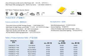
Product Overview
The 3020 series represents a mid-power LED solution designed for general lighting applications, offering an optimal balance between luminous efficacy, cost-effectiveness, and reliability. Housed in a Thermally Enhanced Epoxy Molding Compound (EMC) package, this LED is engineered to deliver consistent performance in a compact 3.0mm x 2.0mm footprint. The series is characterized by its high lumen-per-watt and lumen-per-dollar ratios, making it a compelling choice for cost-sensitive yet performance-oriented lighting designs.
The core positioning of this product is within the retrofit and new-build general lighting markets, including indoor and outdoor applications. Its primary advantages stem from the EMC packaging material, which offers superior thermal management compared to traditional plastics, allowing for higher drive currents and improved longevity. The LED is rated for a nominal power of 0.5W but can be driven up to 0.8W under appropriate thermal conditions, providing design flexibility.
The target market encompasses a wide range of lighting segments: direct replacements for traditional incandescent and fluorescent lamps in retrofit projects, primary light sources for residential and commercial general lighting, backlighting for signage, and architectural or decorative lighting where color quality and reliability are paramount.
In-Depth Technical Parameter Analysis
Photometric and Color Characteristics
The electro-optical performance is specified under standard test conditions of 25°C ambient temperature and 60% relative humidity at a drive current of 80mA. The product family offers Correlated Color Temperature (CCT) options spanning from Warm White (2725K) to Cool White (7040K), detailed in the product selection table. All variants maintain a minimum Color Rendering Index (CRI or Ra) of 80, ensuring good color fidelity for general illumination. Typical luminous flux values range from 54 lumens to 66 lumens at 80mA, depending on the CCT bin. It is critical to note the stated measurement tolerances: ±7% for luminous flux and ±2 for CRI. The CCT is derived from the CIE 1931 chromaticity diagram.
Electrical and Thermal Parameters
The key electrical parameters define the operational envelope of the LED. The typical forward voltage (VF) is 6.6V at 80mA, with a tolerance of ±0.1V. The absolute maximum forward current is 120mA, with a pulsed current (IFP) rating of 200mA for pulses ≤100µs and a duty cycle ≤1/10. The maximum power dissipation (PD) is specified as 816mW. The reverse voltage (VR) withstand capability is 5V.
Thermal performance is crucial for reliability. The thermal resistance from the junction to the solder point (RθJ-SP) is typically 21°C/W. This parameter directly links the operating junction temperature to the board temperature. The maximum allowable junction temperature (Tj) is 115°C. The device features a wide viewing angle (2θ1/2) of 110 degrees, providing a broad, uniform light distribution. Electrostatic discharge (ESD) protection is compliant with the Human Body Model (HBM) up to 1000V.
Absolute Maximum Ratings
Adherence to Absolute Maximum Ratings is non-negotiable for device reliability. Exceeding these limits may cause permanent damage. The ratings are: Forward Current (IF): 120mA; Pulse Forward Current (IFP): 200mA; Power Dissipation (PD): 816mW; Reverse Voltage (VR): 5V; Operating Temperature (Topr): -40°C to +85°C; Storage Temperature (Tstg): -40°C to +85°C; Junction Temperature (Tj): 115°C; Soldering Temperature (Tsld): 230°C or 260°C for 10 seconds (reflow profile dependent).
Binning System Explanation
Color / CCT Binning
The LEDs are sorted into precise color bins to ensure consistency within a lighting fixture. The binning structure for color coordinates follows an elliptical system on the CIE 1931 chromaticity diagram. Each bin (e.g., 27M5, 30M5) is defined by a center point (x, y coordinates), semi-major axis (a), semi-minor axis (b), and an angle of rotation (Φ). The system is aligned with the Energy Star program requirements for the 2600K to 7000K range. The measurement uncertainty for color coordinates is ±0.007. This tight binning minimizes visible color differences between individual LEDs in an array.
Luminous Flux Binning
To manage brightness uniformity, LEDs are also binned according to their luminous flux output at 80mA. The flux is categorized into codes (E7, E8, E9, F1), each representing a specific lumen range (e.g., E8: 58-62 lm, E9: 62-66 lm, F1: 66-70 lm). The applicable flux bin for a given LED depends on its color bin. This two-dimensional binning (color and flux) allows designers to select LEDs that match both the chromaticity and brightness requirements of their application.
Forward Voltage Binning
Forward voltage is sorted into three bins to aid in driver design and current matching in parallel strings. The bins are: Code C (5.5V - 6.0V), Code D (6.0V - 6.5V), and Code E (6.5V - 7.0V), measured at 80mA with a tolerance of ±0.1V. Selecting LEDs from the same voltage bin can help ensure more uniform current distribution and thermal performance in multi-LED systems.
Performance Curve Analysis
The datasheet provides several key graphs for design analysis. The Relative Spectral Distribution plot shows the emission spectrum, which is typical for a phosphor-converted white LED, with a blue pump peak and a broad yellow phosphor emission. The Viewing Angle Distribution confirms the Lambertian-like emission pattern with the 110-degree half-angle.
The Forward Current Characteristics are critical. The IF vs. Relative Luminous Flux curve shows that light output increases sub-linearly with current, with efficacy typically decreasing at higher currents due to increased heat and droop. The Forward Voltage vs. Forward Current (IV) curve is essential for driver design, showing the diode's exponential V-I relationship.
Temperature characteristics are vital for real-world performance. The graph of Ambient Temperature (Ta) vs. Relative Luminous Flux illustrates light output depreciation as the ambient (and consequently junction) temperature rises. The Ta vs. Forward Voltage curve shows the negative temperature coefficient of VF. The Junction Temperature graph plotting Ta against relative flux and forward voltage further elucidates these thermal dependencies. Perhaps most importantly, the Maximum Forward Current vs. Ambient Temperature derating curve dictates the maximum safe operating current at elevated ambient temperatures to prevent exceeding the Tj max of 115°C.
The CIE Chromaticity Diagram visually represents the color bins (27M5, 30M5, etc.) as ellipses on the black-body locus, providing a clear reference for color selection and binning boundaries.
Mechanical and Packaging Information
The LED utilizes a surface-mount device (SMD) package with dimensions of approximately 3.0mm in length and 2.0mm in width. The mechanical drawing provides detailed dimensions, including pad spacing, component height, and solder pad geometry. All dimensions are in millimeters with an undefined tolerance of ±0.2mm. The drawing is presented at a 1:1 scale for accurate reference. The package features two anode and two cathode terminals, facilitating robust solder joint formation and improved thermal conduction to the PCB. The polarity is clearly marked on the package itself, typically with a cathode indicator such as a notch or a green marking.
Soldering and Assembly Guidelines
The component is suitable for lead-free reflow soldering processes. The maximum soldering temperature is specified as 230°C or 260°C peak for a duration of 10 seconds, depending on the specific reflow profile used (e.g., SnAgCu solder). It is imperative to follow a recommended reflow profile with controlled ramp-up and cool-down rates to minimize thermal shock and prevent package cracking or delamination. The moisture sensitivity level (MSL) is not explicitly stated in the provided content, but for EMC packages, it is generally recommended to bake the components if they have been exposed to ambient conditions for extended periods before reflow to avoid "popcorning." Storage should be in a dry, controlled environment within the specified -40°C to +85°C temperature range.
Application Recommendations
Typical Application Scenarios
- Retrofit Lamps: Ideal for LED bulbs and tubes designed to replace incandescent, halogen, or fluorescent lamps, leveraging its efficacy and cost structure.
- General Lighting: Suitable for downlights, panel lights, troffers, and other fixtures in residential, office, and commercial spaces.
- Signage and Backlighting: Effective for indoor and outdoor sign illumination due to its good color rendering and reliability.
- Architectural/Decorative Lighting: Can be used in coves, shelves, and accent lighting where consistent color and smooth beam are important.
Design Considerations
- Thermal Management: The 21°C/W thermal resistance necessitates an effective PCB thermal design. Use of metal-core PCBs (MCPCBs) or thermally enhanced FR4 with sufficient copper area is recommended to keep the solder point temperature low, thereby maintaining light output, color stability, and long-term reliability.
- Current Driving: While rated up to 120mA, operating at or below 80mA is typical for balancing efficacy, lifetime, and thermal load. Use a constant-current LED driver for stable operation.
- Optics: The 110-degree viewing angle is quite broad. Secondary optics (lenses, reflectors) may be required to achieve specific beam patterns.
- Binning Selection: For multi-LED fixtures, specify tight color and flux bins (e.g., within a single ellipse code) to ensure visual uniformity. Consider voltage binning if LEDs are placed in parallel strings.
Technical Comparison and Differentiation
Compared to traditional mid-power LEDs in PPA (Polyphthalamide) or PCT (Polycyclohexylenedimethylene Terephthalate) packages, the key differentiator of this 3020 EMC series is its superior thermal performance. The EMC material has higher thermal conductivity and can withstand higher junction temperatures without yellowing or degradation. This allows for:
- Higher Drive Capability: Ability to be driven at higher currents (up to 0.8W) while maintaining reliability.
- Improved Lumen Maintenance: Better resistance to lumen depreciation (L70, L90) over time due to reduced thermal stress on the phosphor and die.
- Longer Lifespan: The enhanced thermal path slows the rate of internal degradation mechanisms.
- Cost-Effectiveness: Provides a performance level closer to high-power LEDs but at a mid-power price point and with simpler drive requirements.
Frequently Asked Questions (Based on Technical Parameters)
Q: What is the actual power consumption at the typical operating point?
A: At the test condition of 80mA and a typical VF of 6.6V, the power consumption is 0.528W (80mA * 6.6V).
Q: How does light output change with temperature?
A: Luminous flux decreases as junction temperature increases. The derating curve (Fig. 6) quantifies this relationship. Proper heatsinking is essential to minimize output loss in warm environments.
Q: Can I drive this LED at 120mA continuously?
A: While 120mA is the absolute maximum rating, continuous operation at this current requires exceptional thermal management to keep the junction temperature below 115°C. For most designs, operating at or below 80-100mA is recommended for optimal lifetime and efficacy.
Q: What is the difference between the "Typ." and "Min." luminous flux values?
A: The "Typical" value represents the average or expected output for that bin. The "Minimum" value is the lowest output guaranteed for LEDs sorted into that specific flux bin code (e.g., E9). Designers should use the minimum value for conservative system lumen calculations.
Q: How do I interpret the color bin code, e.g., '30M5'?
A: The code defines a specific ellipse on the CIE chart. The first two digits often relate to the CCT (e.g., '30' approximates 3000K nominal), while the letter and number define the ellipse size and position relative to the black-body locus. Refer to Table 5 for the exact center coordinates and ellipse parameters.
Design and Usage Case Study
Scenario: Designing a 1200lm LED Panel Light for Office Use.
A designer targets a 600mm x 600mm panel light with a neutral white color (4000K, CRI >80) and an efficacy of 100 lm/W. Using the 3020 LED from the 40M5 color bin with a typical flux of 66 lm at 80mA (0.528W), the single-LED efficacy is approximately 125 lm/W. To achieve 1200lm, approximately 19 LEDs are needed (1200 lm / 66 lm per LED). Allowing for system losses (optics, thermal), 24 LEDs might be used in a 6x4 array.
The LEDs would be mounted on an aluminum MCPCB. The total system power would be roughly 24 * 0.528W = ~12.7W. A constant-current driver outputting 80mA with a voltage range covering 24 LEDs in series (24 * ~6.6V = ~158V) would be selected. Thermal simulation would be performed to ensure the MCPCB design keeps the LED solder point temperature sufficiently low to maintain >90% of initial lumen output at the fixture's rated operating temperature. By specifying all LEDs from the 40M5 color bin and a single flux bin (e.g., F1), excellent color and brightness uniformity across the panel would be achieved.
Operating Principle Introduction
This is a phosphor-converted white LED. The fundamental operation involves a semiconductor chip, typically made of indium gallium nitride (InGaN), which emits blue light when forward biased (electroluminescence). This blue light is partially absorbed by a cerium-doped yttrium aluminum garnet (YAG:Ce) phosphor layer deposited over the chip. The phosphor down-converts a portion of the blue photons into a broad spectrum of yellow light. The combination of the remaining blue light and the emitted yellow light results in the perception of white light. The exact Correlated Color Temperature (CCT) is controlled by varying the phosphor composition and thickness. The EMC package serves to protect the delicate semiconductor die and phosphor, provide mechanical structure, and most importantly, offer a primary path for heat conduction away from the junction to the solder pads and printed circuit board.
Technology Trends
The mid-power LED segment, particularly with EMC packaging, continues to evolve. Key trends observable in this product and the broader market include:
- Increased Efficacy: Ongoing improvements in internal quantum efficiency of the blue die and phosphor conversion efficiency drive higher lm/W outputs.
- Enhanced Color Quality: Beyond CRI (Ra), there is a focus on improving metrics like R9 (saturated red) and TM-30 (Rf, Rg) for better color rendition, especially in retail and museum lighting.
- Higher Power Density: Packages like the 3020 are being driven harder (e.g., 0.8W) while maintaining reliability, blurring the line between mid-power and high-power segments.
- Improved Thermal Materials: Development of EMC compounds with even higher thermal conductivity and better resistance to harsh environments (UV, humidity).
- Miniaturization and Integration: The drive for smaller, denser light sources for applications like automotive lighting and ultra-slim fixtures.
- Smart and Tunable Lighting: While this is a static white LED, the industry is moving towards LEDs that can dynamically adjust CCT and intensity, often requiring more complex multi-chip or phosphor designs.
The 3020 EMC LED sits firmly within these trends, offering a thermally robust, efficient, and cost-effective platform for the current generation of general lighting solutions.
LED Specification Terminology
Complete explanation of LED technical terms
Photoelectric Performance
| Term | Unit/Representation | Simple Explanation | Why Important |
|---|---|---|---|
| Luminous Efficacy | lm/W (lumens per watt) | Light output per watt of electricity, higher means more energy efficient. | Directly determines energy efficiency grade and electricity cost. |
| Luminous Flux | lm (lumens) | Total light emitted by source, commonly called "brightness". | Determines if the light is bright enough. |
| Viewing Angle | ° (degrees), e.g., 120° | Angle where light intensity drops to half, determines beam width. | Affects illumination range and uniformity. |
| CCT (Color Temperature) | K (Kelvin), e.g., 2700K/6500K | Warmth/coolness of light, lower values yellowish/warm, higher whitish/cool. | Determines lighting atmosphere and suitable scenarios. |
| CRI / Ra | Unitless, 0–100 | Ability to render object colors accurately, Ra≥80 is good. | Affects color authenticity, used in high-demand places like malls, museums. |
| SDCM | MacAdam ellipse steps, e.g., "5-step" | Color consistency metric, smaller steps mean more consistent color. | Ensures uniform color across same batch of LEDs. |
| Dominant Wavelength | nm (nanometers), e.g., 620nm (red) | Wavelength corresponding to color of colored LEDs. | Determines hue of red, yellow, green monochrome LEDs. |
| Spectral Distribution | Wavelength vs intensity curve | Shows intensity distribution across wavelengths. | Affects color rendering and quality. |
Electrical Parameters
| Term | Symbol | Simple Explanation | Design Considerations |
|---|---|---|---|
| Forward Voltage | Vf | Minimum voltage to turn on LED, like "starting threshold". | Driver voltage must be ≥Vf, voltages add up for series LEDs. |
| Forward Current | If | Current value for normal LED operation. | Usually constant current drive, current determines brightness & lifespan. |
| Max Pulse Current | Ifp | Peak current tolerable for short periods, used for dimming or flashing. | Pulse width & duty cycle must be strictly controlled to avoid damage. |
| Reverse Voltage | Vr | Max reverse voltage LED can withstand, beyond may cause breakdown. | Circuit must prevent reverse connection or voltage spikes. |
| Thermal Resistance | Rth (°C/W) | Resistance to heat transfer from chip to solder, lower is better. | High thermal resistance requires stronger heat dissipation. |
| ESD Immunity | V (HBM), e.g., 1000V | Ability to withstand electrostatic discharge, higher means less vulnerable. | Anti-static measures needed in production, especially for sensitive LEDs. |
Thermal Management & Reliability
| Term | Key Metric | Simple Explanation | Impact |
|---|---|---|---|
| Junction Temperature | Tj (°C) | Actual operating temperature inside LED chip. | Every 10°C reduction may double lifespan; too high causes light decay, color shift. |
| Lumen Depreciation | L70 / L80 (hours) | Time for brightness to drop to 70% or 80% of initial. | Directly defines LED "service life". |
| Lumen Maintenance | % (e.g., 70%) | Percentage of brightness retained after time. | Indicates brightness retention over long-term use. |
| Color Shift | Δu′v′ or MacAdam ellipse | Degree of color change during use. | Affects color consistency in lighting scenes. |
| Thermal Aging | Material degradation | Deterioration due to long-term high temperature. | May cause brightness drop, color change, or open-circuit failure. |
Packaging & Materials
| Term | Common Types | Simple Explanation | Features & Applications |
|---|---|---|---|
| Package Type | EMC, PPA, Ceramic | Housing material protecting chip, providing optical/thermal interface. | EMC: good heat resistance, low cost; Ceramic: better heat dissipation, longer life. |
| Chip Structure | Front, Flip Chip | Chip electrode arrangement. | Flip chip: better heat dissipation, higher efficacy, for high-power. |
| Phosphor Coating | YAG, Silicate, Nitride | Covers blue chip, converts some to yellow/red, mixes to white. | Different phosphors affect efficacy, CCT, and CRI. |
| Lens/Optics | Flat, Microlens, TIR | Optical structure on surface controlling light distribution. | Determines viewing angle and light distribution curve. |
Quality Control & Binning
| Term | Binning Content | Simple Explanation | Purpose |
|---|---|---|---|
| Luminous Flux Bin | Code e.g., 2G, 2H | Grouped by brightness, each group has min/max lumen values. | Ensures uniform brightness in same batch. |
| Voltage Bin | Code e.g., 6W, 6X | Grouped by forward voltage range. | Facilitates driver matching, improves system efficiency. |
| Color Bin | 5-step MacAdam ellipse | Grouped by color coordinates, ensuring tight range. | Guarantees color consistency, avoids uneven color within fixture. |
| CCT Bin | 2700K, 3000K etc. | Grouped by CCT, each has corresponding coordinate range. | Meets different scene CCT requirements. |
Testing & Certification
| Term | Standard/Test | Simple Explanation | Significance |
|---|---|---|---|
| LM-80 | Lumen maintenance test | Long-term lighting at constant temperature, recording brightness decay. | Used to estimate LED life (with TM-21). |
| TM-21 | Life estimation standard | Estimates life under actual conditions based on LM-80 data. | Provides scientific life prediction. |
| IESNA | Illuminating Engineering Society | Covers optical, electrical, thermal test methods. | Industry-recognized test basis. |
| RoHS / REACH | Environmental certification | Ensures no harmful substances (lead, mercury). | Market access requirement internationally. |
| ENERGY STAR / DLC | Energy efficiency certification | Energy efficiency and performance certification for lighting. | Used in government procurement, subsidy programs, enhances competitiveness. |