Table of Contents
- 1. Product Overview
- 2. In-Depth Technical Parameter Analysis
- 2.1 Electro-Optical Characteristics
- 2.2 Electrical and Thermal Parameters
- 3. Binning System Explanation
- 3.1 Color (CCT) Binning
- 3.2 Luminous Flux Binning
- 3.3 Forward Voltage Binning
- 4. Performance Curve Analysis
- 4.1 IV and Luminous Flux Characteristics
- 4.2 Temperature Dependency
- 4.3 Spectral and Viewing Angle Distribution
- 5. Assembly and Handling Guidelines
- 5.1 Reflow Soldering
- 5.2 Storage and Handling
- 6. Application Notes and Design Considerations
- 6.1 Thermal Management
- 6.2 Electrical Drive
- 6.3 Optical Integration
- 7. Technical Comparison and Advantages
- 8. Frequently Asked Questions (FAQs)
- 9. Design and Usage Case Study
- 10. Technical Principles and Trends
- 10.1 Operating Principle
- 10.2 Industry Trends
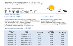
1. Product Overview
This document details the specifications for a series of mid-power LEDs utilizing a 3030 form factor (3.0mm x 3.0mm) and an advanced EMC (Epoxy Molding Compound) package. The series is engineered to deliver an optimal balance of luminous efficacy, reliability, and cost-effectiveness, making it a leading choice in the mid-power segment. The core design philosophy centers on thermal management and optical performance, enabling operation at power levels up to 1.5W.
The primary target markets for this LED series include retrofit lighting solutions designed to replace traditional incandescent or fluorescent lamps, general illumination for residential and commercial spaces, backlighting for indoor and outdoor signage, and architectural or decorative lighting applications where both performance and aesthetic quality are paramount.
2. In-Depth Technical Parameter Analysis
2.1 Electro-Optical Characteristics
All measurements are standardized at a forward current (IF) of 25mA and an ambient temperature (Ta) of 25°C with 60% relative humidity. The product line offers a range of Correlated Color Temperatures (CCT) from warm white (2725K) to cool white (6530K), catering to diverse lighting needs. A minimum Color Rendering Index (CRI or Ra) of 80 ensures good color fidelity for general lighting applications.
The luminous flux output is categorized by both color bin and flux rank. Typical luminous flux values range from approximately 122 lumens to 156 lumens at the test condition of 25mA, depending on the specific CCT and flux bin. It is critical to note the stated measurement tolerances: ±7% for luminous flux and ±2 for CRI. The forward voltage (VF) typically falls between 5.0V and 5.4V at 25mA, with a specified measurement tolerance of ±0.5V.
2.2 Electrical and Thermal Parameters
The absolute maximum ratings define the operational boundaries for reliable performance. The maximum continuous forward current (IF) is 30mA, with a pulsed forward current (IFP) of 40mA allowed under specific conditions (pulse width ≤ 100µs, duty cycle ≤ 1/10). The maximum power dissipation (PD) is 1.5W. Exceeding these ratings may cause permanent degradation or failure.
Thermal management is a key strength of the EMC package. The thermal resistance from the junction to the solder point (Rth j-sp) is specified at a typical value of 11 °C/W. This low thermal resistance facilitates efficient heat transfer from the LED chip to the printed circuit board (PCB), helping to maintain a lower junction temperature (Tj), which is critical for long-term lumen maintenance and reliability. The maximum allowable junction temperature is 115°C.
3. Binning System Explanation
3.1 Color (CCT) Binning
The LEDs are meticulously sorted into precise color bins based on their chromaticity coordinates on the CIE 1931 diagram. The binning structure for CCTs between 2600K and 7000K follows the Energy Star standard, ensuring color consistency within a defined area. Each color code (e.g., 27M5, 30M5) corresponds to a specific center point (x, y coordinates) and an elliptical tolerance area defined by major/minor axes (a, b) and an angle (φ). The measurement uncertainty for color coordinates is ±0.007.
3.2 Luminous Flux Binning
In addition to color, LEDs are further sorted by their luminous flux output at the standard test current. Flux ranks are designated by codes (e.g., 2E, 2F, 2G, 2H), each representing a specific lumen range (e.g., 122-130 lm, 130-139 lm). This two-dimensional binning (color and flux) allows designers to select components that meet both the chromaticity and brightness requirements of their application, ensuring uniformity in the final lighting product.
3.3 Forward Voltage Binning
Forward voltage is also categorized to aid in circuit design, particularly for applications involving multiple LEDs in series. Voltage bins are defined by codes (e.g., 1, 2) with specified minimum and maximum voltage ranges (e.g., 4.6-4.8V, 4.8-5.0V). Matching VF bins can help achieve more uniform current distribution and simplified driver design.
4. Performance Curve Analysis
4.1 IV and Luminous Flux Characteristics
Figure 3 illustrates the relationship between forward current and relative luminous flux. The output is sub-linear; increasing current beyond the recommended 25-30mA range yields diminishing returns in light output while significantly increasing heat generation and stress on the device. Figure 4 shows the forward voltage versus current curve, which is essential for designing the appropriate current-limiting circuitry.
4.2 Temperature Dependency
The performance of LEDs is highly temperature-sensitive. Figure 6 demonstrates that relative luminous flux decreases as ambient temperature (Ta) increases. Figure 7 shows that forward voltage typically decreases with rising temperature. Figure 5 details the shift in chromaticity coordinates (CIE x, y) with temperature, which is crucial for applications requiring stable color points across operating conditions. Figure 8 is critical for thermal design, showing the derating curve for maximum allowable forward current as a function of ambient temperature for two different junction-to-ambient thermal resistance scenarios (35°C/W and 55°C/W).
4.3 Spectral and Viewing Angle Distribution
Figure 1 provides the relative spectral power distribution, which defines the light's color quality. Figure 2 depicts the spatial radiation pattern (viewing angle distribution). The typical viewing angle (2θ1/2), where intensity is half the peak value, is 110 degrees, indicating a wide, Lambertian-like emission pattern suitable for general diffuse lighting.
5. Assembly and Handling Guidelines
5.1 Reflow Soldering
These LEDs are compatible with lead-free reflow soldering processes. The maximum soldering temperature profile must not exceed 230°C or 260°C for a duration of 10 seconds, as specified in the absolute maximum ratings. It is imperative to follow the recommended reflow profile provided by the manufacturer to prevent thermal shock or damage to the EMC package and internal die attach.
5.2 Storage and Handling
The recommended storage temperature range is -40°C to +85°C. To prevent moisture absorption, which can cause popcorning during reflow, LEDs should be stored in a dry environment, typically in sealed moisture barrier bags with desiccant. Standard ESD (Electrostatic Discharge) precautions should be observed during handling, as the devices have an ESD withstand voltage of 1000V (Human Body Model).
6. Application Notes and Design Considerations
6.1 Thermal Management
Effective heat sinking is the single most important factor for achieving rated performance and longevity. The low 11 °C/W junction-to-solder point thermal resistance is only effective if the PCB and system design facilitate heat dissipation. Use of metal-core PCBs (MCPCBs) or boards with adequate thermal vias is strongly recommended for applications operating at or near the maximum current/power. The derating curve (Fig. 8) must be used to determine the safe operating current for the actual thermal environment of the application.
6.2 Electrical Drive
A constant current driver is mandatory for reliable operation. The driver should be designed to supply a stable current up to the maximum of 30mA, accounting for the forward voltage bin and its negative temperature coefficient. For designs using multiple LEDs in series, consider the voltage binning to ensure the total string voltage is within the driver's output range. Parallel connections are generally not recommended without additional balancing circuitry due to VF variations.
6.3 Optical Integration
The wide 110-degree viewing angle makes these LEDs suitable for applications requiring broad, even illumination without secondary optics. For directional lighting, appropriate primary optics (lenses) or reflectors can be used. The high CRI (≥80) makes them excellent for retail lighting, task lighting, and other environments where accurate color perception is important.
7. Technical Comparison and Advantages
The key differentiator of this 3030 EMC series lies in its package technology. Compared to traditional PPA (Polyphthalamide) or PCT plastics, the EMC material offers superior thermal conductivity, higher temperature resistance, and better resistance to yellowing and degradation from UV exposure and heat. This translates to more stable optical performance over the lifetime of the LED, maintaining both lumen output and color point better than plastic-packaged alternatives.
The combination of the robust EMC package, high luminous efficacy, and precise multi-dimensional binning provides a significant advantage in applications demanding high reliability, long life, and consistent quality, such as commercial lighting fixtures and outdoor signage.
8. Frequently Asked Questions (FAQs)
Q: What is the actual power consumption at the typical operating point?
A: At the test condition of IF=25mA and VF=5.4V (typical max), the power is 25mA * 5.4V = 135mW. The "1.2W Series" designation refers to its capability and thermal package rating, not the standard operating point.
Q: How does the luminous flux change if I drive the LED at 30mA instead of 25mA?
A: Refer to Figure 3. The relative luminous flux increases with current but not linearly. Driving at 30mA will yield more light but also generate significantly more heat. You must ensure the junction temperature remains below 115°C by implementing excellent thermal management, as per the derating curve in Figure 8.
Q: Can I use these LEDs for outdoor applications?
A: Yes, the EMC package offers good environmental resistance. However, for outdoor use, the entire luminaire must be properly sealed and designed to manage condensation and environmental stresses. The operating temperature range of -40°C to +85°C supports most outdoor conditions.
Q: Why is the forward voltage tolerance ±0.5V important?
A: This tolerance impacts the design of the power supply, especially when connecting multiple LEDs in series. The driver must accommodate the total possible voltage range of the string. Selecting LEDs from the same voltage bin (Table 7) can simplify driver design and improve system efficiency.
9. Design and Usage Case Study
Scenario: Designing a 1200lm LED Panel Light for Office Use.
A designer aims to create a 600mm x 600mm LED panel light with a neutral white color (4000K, CRI>80) and an output of 1200 lumens.
Component Selection: The designer selects the T3C40821C-**AA model (Neutral White, 3985K typical). From Table 6, for the 40M5 color bin, a flux rank of 2H offers 148-156 lumens at 25mA. Choosing the typical value of 152 lm for calculation.
Quantity Calculation: To achieve 1200 lm, approximately 1200 lm / 152 lm per LED ≈ 8 LEDs are needed at 25mA each.
Thermal & Electrical Design: The 8 LEDs will be arranged on an aluminum MCPCB. Total power at 25mA and typical VF (5.2V): 8 * (0.025A * 5.2V) = 1.04W. The thermal design must ensure the LED solder point temperature remains low enough to keep the junction below 115°C, utilizing the Rth j-sp of 11°C/W. A constant current driver outputting 25mA with a voltage compliance covering 8 * VF (considering bin 2: 4.8-5.0V) is selected.
Outcome: This design leverages the LED's high efficacy and EMC thermal performance to create a reliable, efficient, and uniform office lighting fixture.
10. Technical Principles and Trends
10.1 Operating Principle
These LEDs are based on semiconductor technology. When a forward voltage is applied across the p-n junction, electrons and holes recombine, releasing energy in the form of photons (light). The specific materials and structure of the semiconductor layers determine the wavelength (color) of the emitted light. A phosphor coating is applied to the blue-emitting chip to convert a portion of the blue light into longer wavelengths, creating the broad spectrum of white light with the desired CCT and CRI.
10.2 Industry Trends
The mid-power LED segment continues to evolve towards higher efficacy (lumens per watt) and improved reliability at competitive cost points. Key trends include the widespread adoption of EMC and other ceramic-like package materials for better thermal performance and longevity. There is also a strong focus on enhancing color quality and consistency, with tighter binning standards and higher CRI options becoming commonplace. Furthermore, driver integration and smart controllability are becoming increasingly important for next-generation lighting systems. The 3030 EMC platform represents a mature and optimized solution within these ongoing industry developments.
LED Specification Terminology
Complete explanation of LED technical terms
Photoelectric Performance
| Term | Unit/Representation | Simple Explanation | Why Important |
|---|---|---|---|
| Luminous Efficacy | lm/W (lumens per watt) | Light output per watt of electricity, higher means more energy efficient. | Directly determines energy efficiency grade and electricity cost. |
| Luminous Flux | lm (lumens) | Total light emitted by source, commonly called "brightness". | Determines if the light is bright enough. |
| Viewing Angle | ° (degrees), e.g., 120° | Angle where light intensity drops to half, determines beam width. | Affects illumination range and uniformity. |
| CCT (Color Temperature) | K (Kelvin), e.g., 2700K/6500K | Warmth/coolness of light, lower values yellowish/warm, higher whitish/cool. | Determines lighting atmosphere and suitable scenarios. |
| CRI / Ra | Unitless, 0–100 | Ability to render object colors accurately, Ra≥80 is good. | Affects color authenticity, used in high-demand places like malls, museums. |
| SDCM | MacAdam ellipse steps, e.g., "5-step" | Color consistency metric, smaller steps mean more consistent color. | Ensures uniform color across same batch of LEDs. |
| Dominant Wavelength | nm (nanometers), e.g., 620nm (red) | Wavelength corresponding to color of colored LEDs. | Determines hue of red, yellow, green monochrome LEDs. |
| Spectral Distribution | Wavelength vs intensity curve | Shows intensity distribution across wavelengths. | Affects color rendering and quality. |
Electrical Parameters
| Term | Symbol | Simple Explanation | Design Considerations |
|---|---|---|---|
| Forward Voltage | Vf | Minimum voltage to turn on LED, like "starting threshold". | Driver voltage must be ≥Vf, voltages add up for series LEDs. |
| Forward Current | If | Current value for normal LED operation. | Usually constant current drive, current determines brightness & lifespan. |
| Max Pulse Current | Ifp | Peak current tolerable for short periods, used for dimming or flashing. | Pulse width & duty cycle must be strictly controlled to avoid damage. |
| Reverse Voltage | Vr | Max reverse voltage LED can withstand, beyond may cause breakdown. | Circuit must prevent reverse connection or voltage spikes. |
| Thermal Resistance | Rth (°C/W) | Resistance to heat transfer from chip to solder, lower is better. | High thermal resistance requires stronger heat dissipation. |
| ESD Immunity | V (HBM), e.g., 1000V | Ability to withstand electrostatic discharge, higher means less vulnerable. | Anti-static measures needed in production, especially for sensitive LEDs. |
Thermal Management & Reliability
| Term | Key Metric | Simple Explanation | Impact |
|---|---|---|---|
| Junction Temperature | Tj (°C) | Actual operating temperature inside LED chip. | Every 10°C reduction may double lifespan; too high causes light decay, color shift. |
| Lumen Depreciation | L70 / L80 (hours) | Time for brightness to drop to 70% or 80% of initial. | Directly defines LED "service life". |
| Lumen Maintenance | % (e.g., 70%) | Percentage of brightness retained after time. | Indicates brightness retention over long-term use. |
| Color Shift | Δu′v′ or MacAdam ellipse | Degree of color change during use. | Affects color consistency in lighting scenes. |
| Thermal Aging | Material degradation | Deterioration due to long-term high temperature. | May cause brightness drop, color change, or open-circuit failure. |
Packaging & Materials
| Term | Common Types | Simple Explanation | Features & Applications |
|---|---|---|---|
| Package Type | EMC, PPA, Ceramic | Housing material protecting chip, providing optical/thermal interface. | EMC: good heat resistance, low cost; Ceramic: better heat dissipation, longer life. |
| Chip Structure | Front, Flip Chip | Chip electrode arrangement. | Flip chip: better heat dissipation, higher efficacy, for high-power. |
| Phosphor Coating | YAG, Silicate, Nitride | Covers blue chip, converts some to yellow/red, mixes to white. | Different phosphors affect efficacy, CCT, and CRI. |
| Lens/Optics | Flat, Microlens, TIR | Optical structure on surface controlling light distribution. | Determines viewing angle and light distribution curve. |
Quality Control & Binning
| Term | Binning Content | Simple Explanation | Purpose |
|---|---|---|---|
| Luminous Flux Bin | Code e.g., 2G, 2H | Grouped by brightness, each group has min/max lumen values. | Ensures uniform brightness in same batch. |
| Voltage Bin | Code e.g., 6W, 6X | Grouped by forward voltage range. | Facilitates driver matching, improves system efficiency. |
| Color Bin | 5-step MacAdam ellipse | Grouped by color coordinates, ensuring tight range. | Guarantees color consistency, avoids uneven color within fixture. |
| CCT Bin | 2700K, 3000K etc. | Grouped by CCT, each has corresponding coordinate range. | Meets different scene CCT requirements. |
Testing & Certification
| Term | Standard/Test | Simple Explanation | Significance |
|---|---|---|---|
| LM-80 | Lumen maintenance test | Long-term lighting at constant temperature, recording brightness decay. | Used to estimate LED life (with TM-21). |
| TM-21 | Life estimation standard | Estimates life under actual conditions based on LM-80 data. | Provides scientific life prediction. |
| IESNA | Illuminating Engineering Society | Covers optical, electrical, thermal test methods. | Industry-recognized test basis. |
| RoHS / REACH | Environmental certification | Ensures no harmful substances (lead, mercury). | Market access requirement internationally. |
| ENERGY STAR / DLC | Energy efficiency certification | Energy efficiency and performance certification for lighting. | Used in government procurement, subsidy programs, enhances competitiveness. |