1. Product Overview
This document details the specifications for a high-luminosity white LED lamp. The device is designed for applications demanding significant light output from a compact, industry-standard package. Its core advantage lies in the combination of a high-performance InGaN semiconductor chip with a phosphor conversion system to produce white light, all housed in a robust and widely adopted form factor.
2. Key Features and Description
2.1 Features
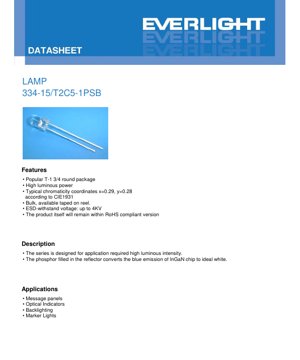
- Industry-standard T-1 3/4 (approximately 5mm) round package.
- High luminous power output.
- Typical chromaticity coordinates: x=0.29, y=0.28 (CIE 1931).
- Available in bulk or taped on reel for automated assembly.
- Electrostatic discharge (ESD) withstand voltage: up to 4KV (Human Body Model).
- Compliant with relevant environmental regulations.
2.2 Description
The LED series is engineered specifically for scenarios requiring high luminous intensity. White light is generated through a phosphor-converted method: the blue light emitted from the indium gallium nitride (InGaN) chip is absorbed by a phosphor material filled in the reflector cup, which then re-emits a broader spectrum of light, resulting in the perception of white light. The water-clear resin lens aids in maximizing light extraction.
3. Absolute Maximum Ratings
The following ratings define the limits beyond which permanent damage to the device may occur. Operation under or at these conditions is not guaranteed.
| Parameter | Symbol | Rating | Unit |
|---|---|---|---|
| Continuous Forward Current | IF | 30 | mA |
| Peak Forward Current (Duty 1/10 @ 1kHz) | IFP | 100 | mA |
| Reverse Voltage | VR | 5 | V |
| Power Dissipation | Pd | 110 | mW |
| Operating Temperature | Topr | -40 to +85 | °C |
| Storage Temperature | Tstg | -40 to +100 | °C |
| ESD (HBM) | ESD | 4000 | V |
| Zener Reverse Current | Iz | 100 | mA |
| Soldering Temperature (5 sec max) | Tsol | 260 | °C |
4. Electro-Optical Characteristics
These parameters are measured at an ambient temperature (Ta) of 25°C and represent typical device performance under specified test conditions.
| Parameter | Symbol | Min. | Typ. | Max. | Unit | Condition |
|---|---|---|---|---|---|---|
| Forward Voltage | VF | 2.8 | -- | 3.6 | V | IF = 20mA |
| Zener Reverse Voltage | Vz | 5.2 | -- | -- | V | Iz = 5mA |
| Reverse Current | IR | -- | -- | 50 | µA | VR = 5V |
| Luminous Intensity | IV | 2850 | -- | 7150 | mcd | IF = 20mA |
| Viewing Angle (2θ1/2) | -- | -- | 50 | -- | deg | IF = 20mA |
| Chromaticity Coordinate x | x | -- | 0.29 | -- | -- | IF = 20mA |
| Chromaticity Coordinate y | y | -- | 0.28 | -- | -- | IF = 20mA |
5. Binning System Explanation
To ensure consistency in applications, LEDs are sorted (binned) based on key performance parameters.
5.1 Luminous Intensity Bins
LEDs are categorized into bins defining a minimum and maximum luminous intensity measured at 20mA. The tolerance is ±10%.
| Bin Code | Min. (mcd) | Max. (mcd) |
|---|---|---|
| P | 2850 | 3600 |
| Q | 3600 | 4500 |
| R | 4500 | 5650 |
| S | 5650 | 7150 |
5.2 Forward Voltage Bins
LEDs are also binned according to their forward voltage drop at 20mA, with a measurement uncertainty of ±0.1V.
| Bin Code | Min. (V) | Max. (V) |
|---|---|---|
| 0 | 2.8 | 3.0 |
| 1 | 3.0 | 3.2 |
| 2 | 3.2 | 3.4 |
| 3 | 3.4 | 3.6 |
5.3 Color (Chromaticity) Bins
The white light color is defined within specific regions on the CIE 1931 chromaticity diagram. The provided color ranks (A1, A0, B3, B4, B5, B6, C0) specify the quadrilateral boundaries for the x and y coordinates, ensuring the emitted white light falls within a controlled color space. The measurement uncertainty for coordinates is ±0.01. A group code (e.g., \"1\") may combine several adjacent color bins for broader selection.
6. Performance Curve Analysis
Graphical data provides insight into device behavior under varying conditions.
6.1 Relative Intensity vs. Wavelength
The spectral power distribution curve shows a broad peak characteristic of phosphor-converted white LEDs, typically centered in the blue region (from the chip) with a broader yellow-green emission from the phosphor.
6.2 Directivity Pattern
The radiation pattern illustrates the 50-degree viewing angle (full width at half maximum), showing the angular distribution of light intensity.
6.3 Forward Current vs. Forward Voltage (I-V Curve)
This curve demonstrates the exponential relationship typical of a diode. The forward voltage increases with current, and designers must ensure the driving circuit provides adequate voltage, especially considering the voltage bin spread.
6.4 Relative Intensity vs. Forward Current
Luminous output increases with forward current but not linearly. Operating above the recommended continuous current (20mA typ.) may yield higher light output but will reduce efficiency and potentially affect long-term reliability due to increased junction temperature.
6.5 Chromaticity Coordinate vs. Forward Current
The color coordinates (x, y) may shift slightly with changes in drive current, which is an important consideration for applications requiring stable color perception across dimming levels.
6.6 Forward Current vs. Ambient Temperature
This derating curve is critical for thermal management. It indicates the maximum allowable forward current as the ambient temperature rises, preventing overheating and ensuring longevity.
7. Mechanical and Package Information
7.1 Package Dimensions
The LED uses a standard T-1 3/4 radial leaded package. Key dimensions include the body diameter (approximately 5mm), lead spacing (measured where leads exit the package), and overall height. A detailed dimensioned drawing is essential for PCB footprint design, ensuring proper fit and alignment. Notes specify a maximum resin protrusion under the flange of 1.5mm and standard dimensional tolerances.
7.2 Polarity Identification
The cathode is typically identified by a flat spot on the rim of the LED lens or by the shorter lead. Correct polarity must be observed during installation.
8. Soldering and Assembly Guidelines
8.1 Lead Forming
- Bend leads at a point at least 3mm from the base of the epoxy bulb.
- Perform lead forming before soldering.
- Avoid stressing the package during forming to prevent internal damage or breakage.
- Cut leadframes at room temperature.
- Ensure PCB holes align perfectly with LED leads to avoid mounting stress.
8.2 Storage Conditions
- Store at ≤30°C and ≤70% Relative Humidity after receipt.
- Standard storage life is 3 months. For longer storage (up to 1 year), use a sealed container with nitrogen and desiccant.
- Avoid rapid temperature changes in humid environments to prevent condensation.
8.3 Soldering Recommendations
Maintain a minimum distance of 3mm from the solder joint to the epoxy bulb.
- Hand Soldering: Iron tip temperature ≤300°C (30W max), soldering time ≤3 seconds.
- Wave/Dip Soldering: Pre-heat ≤100°C (≤60 sec), solder bath ≤260°C for ≤5 seconds.
A recommended soldering temperature profile is provided to minimize thermal shock.
9. Packaging and Ordering Information
9.1 Packing Specification
LEDs are packed in anti-static bags to protect against ESD. Packing quantities are flexible: typically 200-500 pieces per bag, 5 bags per inner carton, and 10 inner cartons per master (outside) carton.
9.2 Label Explanation
Labels on packaging include codes for: Customer Part Number (CPN), Part Number (P/N), Quantity (QTY), combined ranks for Luminous Intensity and Forward Voltage (CAT), Color Rank (HUE), Reference (REF), and Lot Number (LOT No).
9.3 Model Number Designation
The part number 334-15/T2C5-1PSB follows a specific coding system where segments likely indicate the series, color (white), luminous intensity bin, forward voltage bin, and other attributes like packing style. The exact breakdown should be confirmed with the supplier for precise ordering.
10. Application Suggestions
10.1 Typical Applications
- Message Panels & Signage: High intensity makes it suitable for indoor and outdoor informational displays.
- Optical Indicators: Ideal for status indicators on equipment where high visibility is required.
- Backlighting: Can be used for edge-lit or direct backlighting of small panels, icons, or symbols.
- Marker Lights: Suitable for decorative lighting, position markers, or low-level area illumination.
10.2 Design Considerations
- Current Limiting: Always use a series resistor or constant current driver to limit forward current to the desired level (typically 20mA). Account for the forward voltage bin range when calculating resistor values.
- Thermal Management: Although power dissipation is modest, ensure adequate ventilation or heat sinking if operating at high ambient temperatures or near maximum current to maintain performance and lifespan.
- ESD Protection: Implement standard ESD handling procedures during assembly, as specified by the 4KV HBM rating.
- Optical Design: Consider the 50-degree viewing angle when designing lenses or light guides to achieve the desired beam pattern.
11. Technical Comparison and Differentiation
Compared to standard 5mm LEDs, this device emphasizes high luminous intensity. Its key differentiators are the specific InGaN chip technology and phosphor system optimized for brightness. The inclusion of detailed binning for intensity, voltage, and color provides designers with tighter control over application consistency compared to unbinned or broadly binned alternatives. The 4KV ESD rating offers better handling robustness than many basic LEDs.
12. Frequently Asked Questions (Based on Technical Parameters)
12.1 What is the recommended operating current?
The electro-optical characteristics are specified at 20mA, which is the typical recommended operating point for balancing brightness, efficiency, and longevity. It can be driven up to the absolute maximum of 30mA continuous, but with reduced efficacy and increased thermal stress.
12.2 How do I interpret the luminous intensity bins?
If your design requires a minimum brightness, select a bin where the \"Min.\" value meets your requirement. For example, choosing bin \"R\" guarantees an intensity between 4500 and 5650 mcd at 20mA. Using a higher bin (like \"S\") will generally yield brighter LEDs but may come at a higher cost.
12.3 Why is there a Zener Reverse Voltage parameter?
Some LED designs incorporate a reverse-protection Zener diode integrated into the package. The Vz parameter indicates the typical breakdown voltage of this protection device if present. It helps in understanding the reverse characteristics of the component.
12.4 How critical is the 3mm soldering distance rule?
This is very important. Soldering closer than 3mm to the epoxy body can transfer excessive heat, potentially cracking the epoxy lens, degrading the internal phosphor, damaging the wire bonds, or delaminating the chip. This directly impacts reliability and light output.
13. Operational Principle
This is a phosphor-converted white LED. An InGaN semiconductor chip emits blue light when forward biased (electroluminescence). This blue light strikes a layer of yellow (or yellow and red) phosphor particles embedded in the encapsulant. The phosphor absorbs some of the blue photons and re-emits light at longer wavelengths (yellow, red). The combination of the remaining blue light and the broad-spectrum phosphor emission is perceived by the human eye as white light. The exact shade (correlated color temperature) is determined by the ratio of blue to phosphor-converted light, controlled by the phosphor composition and concentration.
14. Technology Trends
The industry trend for discrete indicator LEDs like this one continues towards higher efficiency (more lumens per watt), improved color rendering index (CRI) for better color fidelity, and tighter binning tolerances for greater application consistency. There is also a drive towards more robust packaging to withstand higher temperature reflow soldering processes used in surface-mount assembly, although this particular device is a through-hole component. The underlying InGaN chip technology remains the industry standard for blue and white LEDs due to its high efficiency and reliability.
LED Specification Terminology
Complete explanation of LED technical terms
Photoelectric Performance
| Term | Unit/Representation | Simple Explanation | Why Important |
|---|---|---|---|
| Luminous Efficacy | lm/W (lumens per watt) | Light output per watt of electricity, higher means more energy efficient. | Directly determines energy efficiency grade and electricity cost. |
| Luminous Flux | lm (lumens) | Total light emitted by source, commonly called "brightness". | Determines if the light is bright enough. |
| Viewing Angle | ° (degrees), e.g., 120° | Angle where light intensity drops to half, determines beam width. | Affects illumination range and uniformity. |
| CCT (Color Temperature) | K (Kelvin), e.g., 2700K/6500K | Warmth/coolness of light, lower values yellowish/warm, higher whitish/cool. | Determines lighting atmosphere and suitable scenarios. |
| CRI / Ra | Unitless, 0–100 | Ability to render object colors accurately, Ra≥80 is good. | Affects color authenticity, used in high-demand places like malls, museums. |
| SDCM | MacAdam ellipse steps, e.g., "5-step" | Color consistency metric, smaller steps mean more consistent color. | Ensures uniform color across same batch of LEDs. |
| Dominant Wavelength | nm (nanometers), e.g., 620nm (red) | Wavelength corresponding to color of colored LEDs. | Determines hue of red, yellow, green monochrome LEDs. |
| Spectral Distribution | Wavelength vs intensity curve | Shows intensity distribution across wavelengths. | Affects color rendering and quality. |
Electrical Parameters
| Term | Symbol | Simple Explanation | Design Considerations |
|---|---|---|---|
| Forward Voltage | Vf | Minimum voltage to turn on LED, like "starting threshold". | Driver voltage must be ≥Vf, voltages add up for series LEDs. |
| Forward Current | If | Current value for normal LED operation. | Usually constant current drive, current determines brightness & lifespan. |
| Max Pulse Current | Ifp | Peak current tolerable for short periods, used for dimming or flashing. | Pulse width & duty cycle must be strictly controlled to avoid damage. |
| Reverse Voltage | Vr | Max reverse voltage LED can withstand, beyond may cause breakdown. | Circuit must prevent reverse connection or voltage spikes. |
| Thermal Resistance | Rth (°C/W) | Resistance to heat transfer from chip to solder, lower is better. | High thermal resistance requires stronger heat dissipation. |
| ESD Immunity | V (HBM), e.g., 1000V | Ability to withstand electrostatic discharge, higher means less vulnerable. | Anti-static measures needed in production, especially for sensitive LEDs. |
Thermal Management & Reliability
| Term | Key Metric | Simple Explanation | Impact |
|---|---|---|---|
| Junction Temperature | Tj (°C) | Actual operating temperature inside LED chip. | Every 10°C reduction may double lifespan; too high causes light decay, color shift. |
| Lumen Depreciation | L70 / L80 (hours) | Time for brightness to drop to 70% or 80% of initial. | Directly defines LED "service life". |
| Lumen Maintenance | % (e.g., 70%) | Percentage of brightness retained after time. | Indicates brightness retention over long-term use. |
| Color Shift | Δu′v′ or MacAdam ellipse | Degree of color change during use. | Affects color consistency in lighting scenes. |
| Thermal Aging | Material degradation | Deterioration due to long-term high temperature. | May cause brightness drop, color change, or open-circuit failure. |
Packaging & Materials
| Term | Common Types | Simple Explanation | Features & Applications |
|---|---|---|---|
| Package Type | EMC, PPA, Ceramic | Housing material protecting chip, providing optical/thermal interface. | EMC: good heat resistance, low cost; Ceramic: better heat dissipation, longer life. |
| Chip Structure | Front, Flip Chip | Chip electrode arrangement. | Flip chip: better heat dissipation, higher efficacy, for high-power. |
| Phosphor Coating | YAG, Silicate, Nitride | Covers blue chip, converts some to yellow/red, mixes to white. | Different phosphors affect efficacy, CCT, and CRI. |
| Lens/Optics | Flat, Microlens, TIR | Optical structure on surface controlling light distribution. | Determines viewing angle and light distribution curve. |
Quality Control & Binning
| Term | Binning Content | Simple Explanation | Purpose |
|---|---|---|---|
| Luminous Flux Bin | Code e.g., 2G, 2H | Grouped by brightness, each group has min/max lumen values. | Ensures uniform brightness in same batch. |
| Voltage Bin | Code e.g., 6W, 6X | Grouped by forward voltage range. | Facilitates driver matching, improves system efficiency. |
| Color Bin | 5-step MacAdam ellipse | Grouped by color coordinates, ensuring tight range. | Guarantees color consistency, avoids uneven color within fixture. |
| CCT Bin | 2700K, 3000K etc. | Grouped by CCT, each has corresponding coordinate range. | Meets different scene CCT requirements. |
Testing & Certification
| Term | Standard/Test | Simple Explanation | Significance |
|---|---|---|---|
| LM-80 | Lumen maintenance test | Long-term lighting at constant temperature, recording brightness decay. | Used to estimate LED life (with TM-21). |
| TM-21 | Life estimation standard | Estimates life under actual conditions based on LM-80 data. | Provides scientific life prediction. |
| IESNA | Illuminating Engineering Society | Covers optical, electrical, thermal test methods. | Industry-recognized test basis. |
| RoHS / REACH | Environmental certification | Ensures no harmful substances (lead, mercury). | Market access requirement internationally. |
| ENERGY STAR / DLC | Energy efficiency certification | Energy efficiency and performance certification for lighting. | Used in government procurement, subsidy programs, enhances competitiveness. |